background image

Summary of Contents for 917.292493

Page 1: ...n engine which operates _ differently from previously built engines Before you start the engine read and understand this Owner s Manual IMPORTANT Read and follow all Safety Rules and Instructions before operating this equipment Sears Roebuck and Co Hoffman Estates IL 60179 U S A Visit our Craftsman website www sears com craftsman ...

Page 2: ...duct is in use in the united states This Warranty gives you specific legal rights and you may also have other rights which vary from state to state SEARS ROEBUCK AND CO D 817WA HOFFMAN ESTATES IL 60179 IMPORTANT This cutting machine is capable of amputating hands and feet and throw ing objects Failure to observe the following safety instructions could result in serious injury or death TRAINING Rea...

Page 3: ...dren and pets away Do not overload the machine capacity by attempting to till too deep at too fast a rate Never operate the machine at high speeds on slippery surfaces Look be hind and use care when backing Never allow bystanders near the unit Use only attachments and accessories approved by the manufacturer of the tiller Never operate the tiller without good vis ibility or light Be careful when t...

Page 4: ...rve the safety rules Follow a regular schedule in main taining caring for and using your tiller Follow the instructions under the Main tenance and Storage sections of this Owner s Manual _ WARNING This unit is equipped with an internal combustion engine and should not be used on or near any unimproved forest covered brush covered or grass covered land unless the engine s exhaust system is equipped...

Page 5: ...A socket wrench set will make assembly easier Standard wrench sizes are listed 1 Utility knife 1 Screwdriver 1 Pair of pliers 2 1 2 wrenches OPERATOR S POSITION When right or left hand is mentioned in this manual it means when you are in the operating position standing behind tiller handles Front F I Left _ Right Operator s Position 1 Manual 1 Bottle Engine Oil CONTENTS OF HARDWARE PACK 2 Carriage...

Page 6: ...rews Handle Mount Tine Control INSTALL DEPTH STAKE ASSEMBLY 1 Loosen nut A 2 Insert stake support between engine bracket halves with stake spring down 3 Bolt stake support to engine brackets with bolts lock washers and nuts Tighten securely Tighten nut A 4 Depth stake must move freely If it does not loosen support bolt ngine Bracket Halves Nut A Depth Stake Depth Stake Support Bolt Stake Spring He...

Page 7: ... understand their meaning OR WARNING ON OFF Reverse Tine Control Forward Tine Choke Control Control Depth Stake e Shield Tines Sears tillers conform to the safety standards of the American National Standards Institute FORWARD TINE CONTROL Engages tines in forward direction REVERSE TINE CONTROL Engages tines in reverse direction CHOKE CONTROL Used when starting a cold engine THROTTLE CONTROL Contro...

Page 8: ...ntrol ON DOWN Position Throttle Control Choke TINE OPERATION FORWARD Squeeze forward tine control to handle REVERSE With forward tine control OFF up position pull back and hold reverse tine control TILLING The speed and depth of tilling is regulated by the position of the depth stake and wheel height The depth stake should always be below the wheels for digging It serves as a brake to slow the til...

Page 9: ...mage the fuel system of an engine while in storage To avoid engine problems the fuel system should be emptied before storage of 30 days or longer Drain the gas tank start the engine and let it run until the fuel lines and carburetor are empty Use fresh fuel next season See Storage Instructions for additional information Never use engine or carburetor cleaner products in the fuel tank or permanent ...

Page 10: ...g on the climate rainfall and wind it may be advisable to till the soil at the end of the growing season to further condition the soil Soil conditions are important for proper tilling Tines will not readily penetrate dry hard soil which may contribute to excessive bounce and difficult handling of your tiller Hard soil should be mois tened before tilling however extremely wet soil will ball up or c...

Page 11: ... value from the warranty the operator must maintain tiller as instructed in this manual Some adjustments will need to be made periodically to properly maintain your tiller All adjustments in the Service and Adjust ments section of this manual should be checked at least once each season Once a year you should replace the spark plug clean or replace air filter and check tines and belts for wear A ne...

Page 12: ... Determine temperature range expected before oil change All oil must meet API service classification SF SJ Be sure tiller is on level surface Oil will drain more freely when warm Catch oil in a suitable container 1 Remove drain plug 2 Tip tiller forward to drain oil 3 After oil has drained completely replace oil drain plug and tighten se curely 4 Remove oil filler plug Be careful not to allow dirt...

Page 13: ...ish etc of all foreign matter Keep finished surfaces and wheels free of all gasoline oil etc Protect painted surfaces with auto motive type wax A CAUTION Disconnect spark plug wire from spark plug and place wire where it cannot come into contact with plug TILLER TO ADJUST HANDLE HEIGHT Factory assembly has provided lowest handle height Select handle height best suited for your tilling conditions H...

Page 14: ... is too loose Loosen cable clip and pull cable up to remove slack and retighten clip 8 Recheck in ON position and adjust if necessary NOTE If ON position check required adjustment recheck OFF position ad justment to insure tines do not rotate when control is OFF up Tine Control OFF Body Tine Control ON Position Cable Clip _ Fine Control Cable TO REMOVE BELT GUARD 1 Remove two 2 cap nuts and washer...

Page 15: ...t Forward Motion INSIDE V Belt Bolt Transmission Pulley ENGINE Maintenance repair or replacement of the emission control devices and systems which are being done at the customers ex pense may be performed by any non road engine repair establishment or individual Warranty repairs must be performed by an authorized engine manufacturer s service outlet TO ADJUST CARBURETOR The carburetor has been pre...

Page 16: ...rt the engine and let it run until the fuel lines and carburetor are empty Never use engine or carburetor cleaner products in the fuel tank or permanent damage may occur Use fresh fuel next season NOTE Fuel stabilizer is an acceptable alternative in minimizing the formation of fuel gum deposits during storage Add stabilizer to gasoline in fuel tank or stor age container Always follow the mix ratio...

Page 17: ... several minutes before attempting to start 4 Clean or replace air cleaner cartridge 5 Drain fuel tank and carbure tor and refill tank with fresh gasoline 6 Remove fuel tank and clean 7 Make sure spark plug wire is seated properly on plug 8 Replace spark plug or adjust gap 9 Make necessary adjust ments 1 Place throttle control in FAST position 2 Clean or replace air cleaner cartridge 3 Replace spa...

Page 18: ... too wet 1 Tine control is not engaged 2 V belt not correctly adjusted 3 V belt is off pulley s 1 Tilling too deep 2 Throttle control not properly adjusted 3 Carburetor out of adjustment CORRECTION 1 Check oil level change oil 2 Clean engine air screen 3 Clean cylinder fins airscreen muffler area 4 Remove and clean muffler 5 Adjust carburetor to richer position 1 Moisten ground or wait for more fa...

Page 19: ...as instrucciones de seguridad siguientes se pueden producir lesiones graves o la muerte ENTRENAMIENTO Lea el Manual del Dueff_ocuidadosamente Familiarfcese completamente con los controles y con el uso adecuado del equipo Sepa c6mo parar la unidad y desenganchar los controles rApidamente Nunca permita que los niSos operen el equi po Nunca permita que los adultos operen el equipo sin los conocimient...

Page 20: ...Nunca opere la cultivadora sin buena visibili dad o luz Tenga cuidado al cultivar en terreno duro Los brazos pueden quedarse agarrados en el suelo e impulsar a la cultivadora hacia adelante Si esto sucede suelte los mangos y no restrinja la maquina MANTENIMIENTO Y ALMACENAMIEN TO Mantenga los accesorios y aditamentos de la maquina en buenas condiciones para el funcionamiento Revise las clavijas de...

Page 21: ... unidad viene equipa da con un motor de combusti6n interno y no se debe usar sobre o cerca de un terreno no de sarrollado cubierto de bosques de arbustos o de c6sped a menos que el sistema de escape del motor venga equipado con un amortiguador de chispas que cumpla con las leyes locales o estatales si existen Si se usa un amortigua dor de chispas el operador debe mantenerlo en condiciones de traba...

Page 22: ... con un juego de llaves de tubo Se han enumerado los tamaSos est ndar de las Ilaves 1 Cuchillo para todo uso 1 Par de alicates 1 Desatornillador 2 Llave de 1 2 POSICI _N DEL OPERADOR Cuando en este manual se mencionan los t_rminos lado derecho o lado izquierdo se refiere a cuando usted se encuentra en la posici6n de operaci6n parado a detr s de los mangos de la cultivadora Lado lzquierdo ParteDela...

Page 23: ... los brazos Columna del mango INSTALACION DEL CONJUNTO DE LA ESTACA DE PROFUNDIDAD 1 Afioje la tuercas A 2 Inserte el soporte de la estaca entre las mitades del puntal del motor con el resorte de la estaca hacia abajo 3 Aperen el soporte de la estaca en los pun tales del motor con los pernos hexagonates las arandelas de seguridad y tas tuercas Apri_tetos en forma segura Tambi6n apriete las tuercas...

Page 24: ...la_ Control de la estrangualci6n Estaca de profundidad arr nc or culateo _ __ Control de la J aceleraci6n Defensas de los brazo _ jBrazos Las cultivadoras de Sears cumplen con los est ndares de seguridad del American National Standard Institute Instituto Nacional de Estandares Americano CONTROL DE LOS BRAZOS MARCHA HA CIA ADELANTE Engancha los brazos en la direcci6n de marcha hacia adelante CONTRO...

Page 25: ...undidad dentro del suelo m s profunda serA la excav aci6n realizada con los brazes ESTACA DE PROFUNDIDAD Ajuste la estaca de profundidad removiendo la abrazadera de horquilla y la clavija de horquilla Cambie la estaca de profundidad a la posici6n deseada Vuelva a colocar la clavija de horquilla y la abrazadera de horquilla Para el labrado normal ajuste la estaca de profundidad en el segundo o terc...

Page 26: ...me Evite crear cu alquiera fuente de ignici6n hasta que se hayan desaparecido los gases de la gasolina Limpie el aceite o el combustible derramado No almacene derrame o use gasolina cerca de una llama expuesta IMPORTANTE Cuando se opere en temperatu ras por debajo de 32 F 0 C use gasolina de inviemo limpia y nueva para auedar a asegurar un buen arranque en clima fr o PRECAUCION Combustibles mezcla...

Page 27: ...est tab rando El ajuste adecuado de las ruedas y de la estaca de profundidad se Iogra al probarlas en acci6n y depende de las condiciones det suelo Mientras m s duro o m_ s mojado est6 el suelo menor es la velocidad necesada del mo tor y de los brazes La cultivadora va a correr y saltar sobre el terreno si se usa en estas malas condiciones a una velocidad r pida Si la cultivadora est bien ajustada...

Page 28: ...La meier profundidad de excavaci6n es de l a 3 Probablemente no va a necesitar usar la es taca de profundidad Empiece por inclinar la estaca de profundidad hacia adelante hasta que quede sujeta en el resorte de la estaca Cultive hacia arriba y hacia abajo las filas a una velocidad que le permita a los brazos sacar las raices de la mala hierba y dejar el suelo en condiciones asperas para impedir el...

Page 29: ...el operador tiene que mantener la cultivadora segQn las instrucciones descritas en este manual Hay algunos ajustes que se tienen que hacer en forma peri6dica para poder mantener su cuitivadora adecuadamente Todos los ajustes en la secci6n de Servicio y Ajustes de este manual tienen que ser revisados por lo menos una vez por cada temporada Una vez at aSo cambie la bujia limpie o cambie el filtro de...

Page 30: ...sificaci6n de servicio API SF SJ AsegSrese que la cultivadora est6 en una superficie nivelada El aceite drenar m s f cilmente cuando esta caliente 0tilice un embudo para impedir el derrame de aceite sobre la cultivadora y recoja el aceite en un envase adecuado 1 Remueva el tap6n del drenaje 2 Incline la cultivadora hacia adelante para drenar el aceite 3 Despu6s de que el aceite se haya drenado com...

Page 31: ...Mantenga las superficies pulidas y las ruedas sin derrames de gasolina aceite etc Proteja las superficies pintadas con cera tipo automotriz _I PRECAUCION Desconecte el alambre de la bujia y pdngalo en donde no pueda entrar en contacto con la bujfa CULTIVADORA PARA AJUSTAR LA ALTURA DEL MANGO El montaje en ta fAbrica se ha reatizado usando la altura mAs baja del mango Seleccione la attura del mango...

Page 32: ... Con el control de los brazos en la posici6n de APAGADO OFF arriba empuje ha cia abajo el mango para levantar los brazos fuera del suelo 2 Lentamente tire el mango del arrancador de culateo mientras se observan los brazos Los brazos no deben rotar 3 Si los brazos rotan el alambre interior del cable de control est demasiado apretado extendiendo el resorte inferior y estA engan chando los brazos Sue...

Page 33: ... esta secci6n de este manual 10 Vuelva a colocar la protecci6n de la correa Referencia de vista deiantera Polea de Guia de del braze de guia Polea del motor Correa v de movimiento hacia adelante interior f Polea del motor polea Plieade de marcha atras Peleade gui de la polea marcha hacia 7_ jS adelante Poleade la transmisi6n Correa v de marchaatras Exterior Plieade guia de marcha atras __ _ _ Pole...

Page 34: ...el motor y d_jelo funcionar hasta que las t neas del combustible y el carburador est_n vac os Nunca use los productos para limpieza del carburador o del motor en el estanque de combustible pues se pueden producir dafios permanentes Use combustible nuevo la pr6xima tempo rada AVlSO El estabilizador de combustible es una altemativa aceptable para reducir a un minimo la formaci6n de dep6sitos de goma...

Page 35: ...tro de aire 5 Drene et estanque de combustible y el carburador vuelva a llenar el estanque con gasolina nueva 6 Remueva el estanque de combustible y Iimpielo 7 Aseg_rese que el alambre de la bujia est6 asentado en forma adecuada en _sta 8 Cambie la bujia o ajuste la abertura 9 Haga los ajustes necesarios 1 Ponga el control de 1 aceleraci6n en la posici6n de RAPIDO FAST 2 Limpie o cambie el cartuch...

Page 36: ...sici6n de mezcla mas rica 1 Moje el suelo o espere a que existan condiciones del suelo mAs favorables 2 Ajuste las ruedas y la estaca de profundidad El suelo se hace 1 El terreno esta muy mojado 1 Espere a que existan bolas o se condiciones del suelo mas amon tona favorables 1 La barra de control de la impulsi6n no estA enganchada 2 La correa V no estA ajustada oorrectamente 3 La correa Vesta fuer...

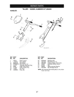
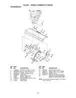
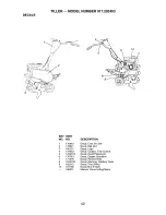
Page 37: ...13 STD533107 Bolt 5 16 18 x 3 4 38 152094 14 181476 Assembly Panel and Tube 43 181580 18 3066J Cable Tine Control 44 180528 19 151229 Lever Control Tine 45 73510600 20 154805 Pin Pivot 21 12000027 Ring Clip DESCRIPTION Retaining Ring Bolt 5 16 18x2 1 2 Locknut Flange 5 16 18 Unc Assembly Handle Column Clip Cable Assembly Reverse Nut Hex Keps 3 8 16 NOTE All component dimensions given in U S inches...

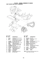
Page 38: ...ex Hd 3 8 16 x 1 3 4 Guard Belt Washer 9 32 x 5 8 x 16 Ga Nut Cap 1 4 20 Bolt Carriage 1 4 20 x 3 4 V Belt Forward Motion V Belt Reverse Ring Retainer Key Square Sheave Transmission flat Bolt Belt Guard KEY PART NO NO DESCRIPTION 20 12000036 Ring Klip 21 STD541237 Nut Hex Jam 3 8 16 22 161806 Pulley Idler 23 175377 Arm Idler 24 STD523712 Belt Hex Head 3 8 16 x 1 1 4 25 106968X Shaft Idler Arm 26 7...

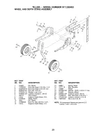
Page 39: ... Hex 5 16 18 Washer Lock 5 16 Locknut w washer 3 8 16 Clip Hairpin Support Depth Stake R H Stake Depth Pin Clevis Bolt Fin Hex 3 8 16 x 1 3 4 Support Depth Stake L H KEY PART NO NO DESCRIPTION 15 5388J Spring Stake 16 121117X Bolt Shoulder 17 9188R Wheel 18 STD551037 Washer 13 32x13 16x11Ga 19 9190R Bracket Wheel 20 STD541437 Locknut Crown 3 8 16 21 74760516 Bolt Hex Head 5 16 18 x 1 22 STD541431 ...

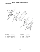
Page 40: ...493 TINE ASSEMBLY 6 2 2 I 6 5 KEY PART NO NO DESCRIPTION 1 156934 Tine Outer R H 2 STD624008 Retainer Spring 3 156932 Tine Inner R H KEY PART NO NO 4 156931 5 156933 6 4929H DESCRIPTION Tine Inner L H Tine Outer L H Pin Clevis 40 ...

Page 41: ...x 13 16 x 11 Locknut w washer 3 8 16 Shield Tine Bracket Engine R H Bracket Engine L H Bolt Hex Head 5 16 18 x 2 3 4 Transmission Spacer Split KEY PART NO NO DESCRIPTION 15 73970500 Nut Hex Lock 5 16 18 16 19091412 Washer 9 32 x 7 8 x12 Gauge 17 19092016 Washer 9 32x1 1 4x16Ga 18 STD551125 Washer Lock 1 4 19 74610412 Bolt Hex 1 4 28 x 3 4 Grade 5 20 Engine See Breakdown Briggs Model No 126402 0206...

Page 42: ...1 4 137653 5 120431X 6 176783 7 171078 8 120075X 9 162215 10 167156 186031 Decal CntrL Pnl Set Decal Belt Grd Decal Logo Decal Caution Tine Control Decal Hand Placement Decal Engine Operation Decal Rewind lntek Decal Warning Rotating Tines Decal Tine Shield Decal B S Intek Manual Owner s Eng Span 42 ...

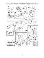
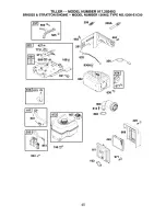
Page 43: ...MBER 917 292493 BRIGGS STRATTON ENGINE MODEL NUMBER 126402 TYPE NO 0206 EIC00 35 _38 36_ 22_ 24 O 415 REQUIRES SPECIAL TOOLS TO INSTALL SEE REPAIR 742 INSTRUCTION MANUAL _ 11058 OWNER S MANUAL I _ _ _ 15A ss2 0 718 43 ...

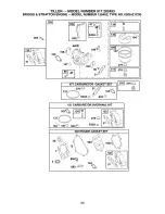
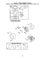
Page 44: ... STRATTON ENGINE MODEL NUMBER 126402 TYPE NO 0206 EIC00 365 633A _ I 633 I 692 _ 95 I 276_ 276_ 977CARBURETO __ GASKETSET J_ 276 121 CARBURETOR OVERHAUL KIT 63 276_ 633A G 104_ 127_ 633_ 358 ENGINE GASKET SET 20 1022_ 3 _ 868 _ 163 883 44 ...

Page 45: ...TILLER MODEL NUMBER 917 292493 BRIGGS STRATTON ENGINE MODEL NUMBER 126402 TYPE NO 0206 E1 COO r s62 _ 1 26 _ _0_ 188_ 621 851 190_ 832 968 334 45 ...

Page 46: ...ER MODEL NUMBER 917 292493 BRIGGS STRATTON ENGINE MODEL NUMBER 126402 TYPE NO 0206 EIC00 1211 65_58 592_ 597 I 1036 EMISSIONS LABEL I 363_ 1005 455 304 305_ 3 1 48 1095 VALVE GASKET SET 9 3 _ 868 1022 51 46 ...

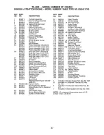
Page 47: ...lded 26 499631 Ring Set Piston Standard 188 690877 Screw Control Bracket 692785 Ring Set Piston 010 O S 189 694543 BalI RockerArm 692786 Ring Set Piston 020 O S 190 692127 Screw Fuel Tank 692787 Ring Set Piston 030 O S 209 691278 Spring Governor 27 691866 Lock Piston Pin 209A 692571 Spring Governor 28 499423 Pin Piston 219 693578 Gear Governor 29 690124 Rod Connecting 220 691724 Washer Governor Ge...

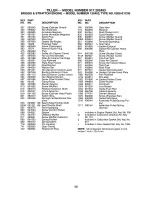
Page 48: ...retor 552 692346 Bushing Governor Crank 993 694088 Gasket Cylinder Head Plate 562 691112 Bolt Governor Control Lever 1005 692592 Fan Flywheel 592 690800 Nut Rewind Starter 1019 694851 Kit Label 597 691696 Screw Pawl Friction Plate 1022 691890 Gasket Rocker Cover 601 95162 Clamp Hose 1023 499924 Cover Rocker 608 497680 Starter Rewind 1026 693517 Rod Push 613 691665 Screw Muffler 1029 691230 Arm Roc...

Page 49: ...49 ...

Page 50: ...50 ...

Page 51: ...51 ...

Page 52: ...nd electronics call or go on hne for the nearest Sears Parts and Repair Center 1 800 488 1222 Anytime day or night U S A only www sears com To purchase a protection agreement U S A or maintenance agreement Canada on a product serviced by Sears 1 800 827 6655 U S A 1 800 361 6665 Canada Para pedtr servlcio de reparaciSn a domtciho y para ordenar ptezas 1 888 SU HOGAR sM 1 888 784 6427 Au Canada pou...

Reviews: