background image

Summary of Contents for 917.293320

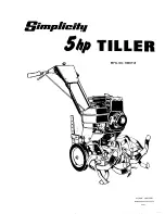
Page 1: ...AR TINE WITH DUAL ROTATING TINES TILLER Model No 917 293320 Safety Assembly Operation Maintenance Espa_ol Repair Parts CAUTION Read and follow all Safety Rules and Instructions before operating this equipment Sears Roebuck and Co Hoffman Estates IL 60179 ...

Page 2: ...nty gives you specific legal rights and you may also have other rights which vary from state to state SEARS ROEBUCKAND CO D 817WA HOFFMAN ESTATES IL 60179 TRAINING Read the Owner s Manual carefully Be thoroughly familiar with the controls and the proper use of the equipment Know how to stop the unit and disengage the controls quickly Never allow children to operate the equipment Never allow adults...

Page 3: ...ll too deep at too fast a rate Never operate the machine at high speeds on slippery surfaces Look behind and use care when backing Never allow bystanders near the unit Use only attachments and accessories approved by the manufacturer of the tiller such as wheel weights counter weights cabs and the like Never operate the tiller without good vis ibility or light Be careful when tilling in hard groun...

Page 4: ...is avail able on this product Contact your nearest Sears store for details CUSTOMER RESPONSIBILITIES Read and observe the safety rules Follow a regular schedule in maintain ing caring for and using your tiller Follow the instructions under the Customer Responsibilities and Stor age sections of this Owner s Manual WARNING This unit is equipped with an internal combustion engine and should not be us...

Page 5: ...ier Standard wrench sizes are listed 1 Utility knife 1 Wire cutter t Tire pressure gauge 1 Screwdriver 1 Pair of pliers 1 9 16 wrench OPERATOR S POSITION When right or left hand is mentioned in this manual it means whenyou are in the operating position standing behind tiller handles FRONT LEFT RIGHT OPERATOR S POSITION CONTENTSOF HARDWARE PACK IIIIIII Y 2 Handle Locks 1 Carriage Bolt 3 8 16 UNC x ...

Page 6: ...le lock remains in gearcase notch Slide handle assembly into position Rotate handle assembly down Insert rear cardage bolt first with head of bolt on L H side of tiller and loosely assem ble Iocknut 6 IW _ _ Hand e Assembly f _ J UP Position _ _ _ J_ _ o Tighten handle lock to ho Loosen Handle_Lock _ __ Lever to Move _ _ d_ Insert pivot bolt in front part of plate and tighten Cut down remaining co...

Page 7: ... with bend of clip on rinht side REMOVE TILLER FROM CRATE Adjust handle assemby to lowest posi tion Be sure lock lever is tightened securely Make sure shift lever indicator is in N neutral position Tilt tiller forward by lifting handle Separate cardboard cover from leveling shield Rotate tiller handle to the dght and pull tiller out of carton Shift Lever Shift od Lk CHECK TIRE PRESSURE The tires o...

Page 8: ...r Shift Lever Indicator Dra Depth Leveling Outer Side Shield Recoil Starter Handle MEETS ANSI SAFETY REQUIREMENTS Our tillers conform to the safety standards of the American National Standards Institute DRIVE CONTROL BAR Used to engage tines DEPTH STAKE Cont _ols depth at which tiller will dig OUTER SIDE SHIELD Adjustable to pro tect small plants from being buried THROTTLE CONTROL Used to control ...

Page 9: ...nd tiller will move forward REVERSE WHEELS ONLY TINES STOPPED DO NOT STAND DIRECTLY BEHIND TILLER Release the drive control bar Move throttle control to SLOW posi tion _ Move shift lever indicator to R reverse position Hold ddve control bar against the handle to start tiller movement DEPTH STAKE The depth stake can be raised or lowered to allow you more versatile tilling and culti vating or to mor...

Page 10: ...e and muffler to cool Disconnect spark plug wire Drain gaso line from fuel tank AROUND THE YARD Release the depth s_takepin Move the dr pth stake down to the top hole for transporting the tiller Place depth stake pin in hole of depth stake to lock in posi tion This prevents tines from scuffing the ground Place hi_ lever indicator in F forward position for transporting Hold the drive control bar ag...

Page 11: ...res but does not start move choke control to half choke position Pull recoil starter handle until engine starts When engine starts slowly move choke control to RUN position as engine warms up NOTE A warm engine requires less chok ing starting Move throttle control to desired running position Allow engine to warm up for a few min utes before engaging tines NOTE If at a high altitude 3000 feet or in...

Page 12: ...a speed which will allow tines to uproot weeds and leave the ground in rough condition promoting no further growth of weeds and grass Do not lean on handle this takes weight off the wheels reduces traction and may cause the tiller to skip over the ground Always lower the drag stake when using the forward rotating tine drive A 0101010 0101010 0101010 0101010 _J _J TINE SHEAR PINS The tine assemblie...

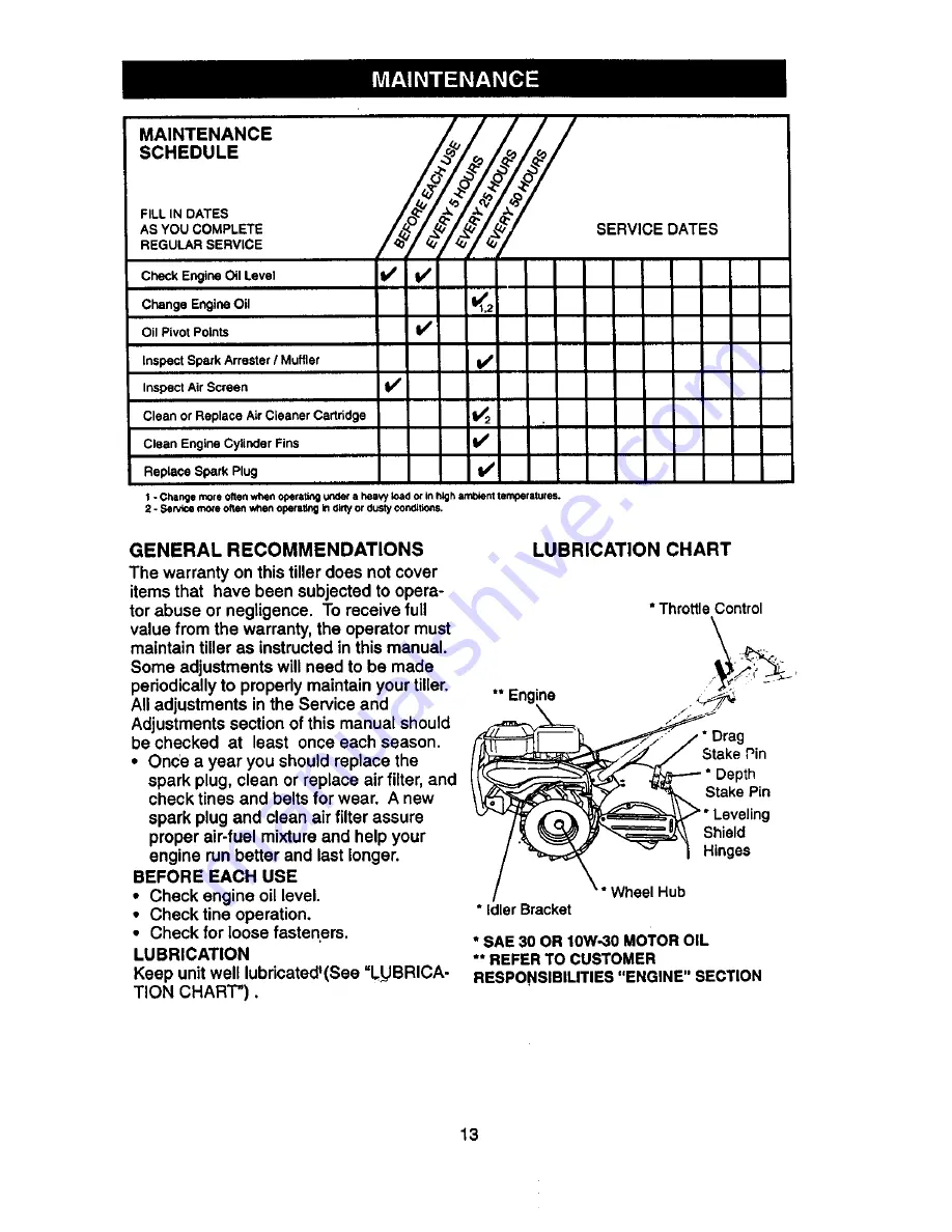
Page 13: ...tructed in this manual Some adjustments will need to be made periodically to propedy maintain your tiller All adjustments in the Service and Adjustments section of this manual should be checked at least once each season Once a year you should replace the spark plug clean or replace air filter and check tines and belts for wear A new spark plug and clean air filter assure proper air fuel mixture an...

Page 14: ... a funnel to prevent oil spill on tiller and catch oil in a suitable container Remove oil drain plug Be careful not to allow dirt to enter the engine For easier removal of plug use 7 16 12 Pt socket with extension rip tiller forward to drain oil After oil h_s drained completely replace oil drain plug and tighten securely RemOve oil fill plug Refill engine with oil through oil fill tube See CHECK E...

Page 15: ...NSMISSION Your transmission is sealed and will only require lubrication if serviced CLEANING Clean engine wheels finish etc of all foreign matter Keep finished surfaces and wheels free of all gasoline oil etc Protect painted surfaces with automotive type wax We do not recommend using a garden hose to clean your unit unless the muffler air filter and carburetor are covered to keep water out Water i...

Page 16: ...ut I _ _t_ _ _ and W her X_ _ 3 Located _ _ _ _ Behind screws Hairpin Clip and Clevis Pin TO REPLACE GROUND DRIVE BELT Remove belt guard as described in TO REMOVE BELT GUARD Remove old belt by slipping off engine pulley first then remove from transmis sion pulley Place new belt in groove of transmis sion pulley and into engine pulley BELT MUST BE IN GROOVE ON TOP OF IDLER PULLEY NOTE POSITION OF B...

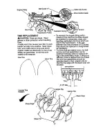
Page 17: ...ing To maintain the superb tilling perfor mance of this machine the tines should be checked for sharpness wear and bending particulady the tines which are next to the transmission If the gap between the tines exceeds 3 1 2 inches they should be replaced or straightened as necessary For tines that are slightly worn the bolt ed tine and hub assemblies can be switched between sides to continue till i...

Page 18: ...with adjustment procedure Loosen cable clamp screw Move throttle lever up until it touches high speed stop and hold in this posi tion Tighten cable clamp screw securely Fuel Tank Clamp Screw TO ADJUS T CARBURETOR The carburetor has been preset at the fac tory and adjustment should not be neces sary However engine performance can be affected by differences in fuel tempera ture altitude or load If t...

Page 19: ...the fuel tank Start the engine and let it run until the fuel lines and carburetor are empty Never use engine or carburetor cleaner products in the fuel tank or permanent damage may occur Use fresh fuel next season NOTE Fuel stabilizer is an acceptable alternative in minimizing the formation of fuel gum deposits during storage Add sta bilizer to gasoline in fuel tank or storage container Always fol...

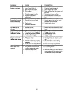
Page 20: ...o start 4 Clean or replace air Cleanercar tridge 5 Drain fuel tank and carburetor and refilltank with fresh gasoline 6 Remove fuel tank and clean 7 Make sure spark plug wire is seat ed propedy on plug 8 Replace spark plug or adjust gap 9 Make necessary adjustments 2 3 4 5 6 1 2 3 4 5 6 7 8 9 10 11 12 13 Place throttle control in FAST position Clean or replace air cleaner car tridge Replace spark p...

Page 21: ...justed 3 Carburetor out of adjustment 1 Drag Stake not lowered in forward rotating till mode 2 Improper filling mode CORRECTION 1 Check oil level change oil 2 Clean engine air screen 3 Clean cylinderfins air screen muf tier area 4 Remove and clean muffler 5 Adjust carburetorto richer posi tion 1 Moisten groundor wait for more favorable soil conditions 2 Adjust depth stake 1 Wait for more favorable...

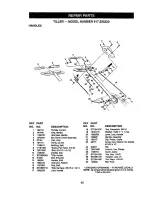
Page 22: ...5 Handle Shift 109313X Grommet Rubber 110702X Rod Shift STD533710 Bolt Carriage 3 8 16 x 1 Gr 5 109229X Lock Handle KEY PART NO NO DESCRIPTION 18 STD541437 Nut Cantedock 3 8 16 19 19131611 Washer 13 32xlx11Ga 20 109228X Lever Lock Handle 21 150628 Handle Assembly 22 165197 Clip Plastic Cable 23 86777 Screw Hex Washer Hd Slotted 10 24 x 1 2 24 9484R Clip 25 73970500 Locknut Hex Range 26 110675X Clu...

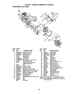
Page 23: ...1i32xlll16xlSGa 43 16 145102 Sheave Transmission 44 17 STD541031 Nut Hex 5 16 18 45 19 12000028 Ring Retainer 46 21 156117 Spacer Split0 327 x 0 42 x 1 220 23 102190X Tire 124258X Rim 795R Tire Valve ts t KEY PART NO NO DESCRIPTION 126875X Rivet Ddlled STD624003 Clip Hairpin 165501X558 Guard Belt 132801 BOlt V 104879X Pulley Idler 12000032 Ring Klip 159229 Bracket Idler 102384X Bolt Hex 5 16 16 x ...

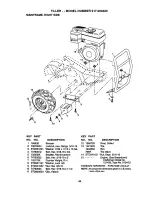
Page 24: ... 74760532 Bolt Hex 5 16 18x2 7 102173X CounterWeight R H 8 STD551137 Washer Lock 3 8 9 STD541037 Nut Hex 3 8 16 10 74760524 Bolt Hex 5 16 18x1 1 2 11 STD624003 Clip Hairpin KEY PART NO NO DESCRIPTION 12 126875X Rivet Drilled 13 102190X Rra 124258X Rim 795R RraValve 14 STD541431 Nut Keps 5 16 18 15 Engine Sea Breakdown Craftsman Model No 121432 Type No 0124 E1 STANDARD HARDWARE PURCHASELOCALLY NOTE...

Page 25: ...134X Chain 35 50 Pitch 30 150737 GroundShaftAssembly KEY PART NO NO DESCRIPTION 31 143008 Bearing Shah GroundDriveR H 32 106388X Spacer 0 70 x 1 00 x 1 150 33 102121X Sprocketand Gear Assembly 34 102112X Shaft Reduction 2nd 35 102101X Screw Whiz Lock 5 15 18 x 3 1 2 36 161524 SprocketAssemblyw Bearing IncludesKey Nos 37 and38 37 1004131K Beadng Needle 38 161525 Sprocket 1i ne 39 161526 Gear Cluste...

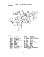
Page 26: ...iage 5 16 18 x 3 4 Gr 5 21 102156X Spdng 22 74930632 Bracket Latch 23 4440J Spdng Depth Stake 24 72140404 Shield TIne 25 6712J St leldAsm 26 109227X Nut Hex 5 16 18 27 163497X558 Washer Lock 5 16 28 120588X Bolt Carriage 5 16 18x1 1 4 31 163498X417 Bracket Shield line Shield Side Outer R H Nut Hex 1 4 20 DESCRIPTION Nut Wing Forged5 16 18 Bolt Cardage 1 4 20 x 1 1 4 Gr 5 Grip Nut Hex 3 8 15 Stake ...

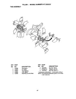
Page 27: ...32673 Pin Shear 3 163500 _ne Cleaning 4 163552 Clip Haiq_in 5 163926 Assembly Hub and Plate KEY PART NO NO DESCRIPTION 6 73610600 Nut Hex 3 8 24 7 STD551137 Washer Lock3 8 8 74610616 Bolt Hex 3 8 24 x 1 STANDARDHARDWARE PURCHASE LOCALLY NOTE All componentdimensionsgiveninU S inches 1 inch 25 4 mm 47 ...

Page 28: ...5 12 166138 13 165837 o 165984 DESCRIPTION Decal Logo Decal Logo Decal Logo Decal Description Decal Caution DriveControl Decal Hand Placement Decal Shift Indicator Decal line Shield Counter Rotating l _nes Decal Warning RotatingTines Decal Tine Drag Stake Decal Tine Shield WarningDom Decal Oper Lub Instructions Decal Tine Depth Stake Manual Owner s English Spanish 48 ...

Page 29: ...917 293320 ENGINE BRIGGS STRAI FON MODEL NUMBER 121432 TYPE NO 0124 E1 3O5 e 478 12 I 1019 LABEL KIT I 11058 OWNER S MANUAL I 51 341 868 40L_ lk REQUIRES SPECIAL TOOLS TO INSTALL SEE REPAIR INSTRUCTION MANUAL 305B 305C 49 ...

Page 30: ...TILLER MODEL NUMBER 917 293320 ENGINE BRIGGS STRATTON MODEL NUMBER 121432 TYPE NO 0124 E1 24 I 634A _ 634 _2_ 110 _ 110_ 5O ...

Page 31: ...TILLER MODEL NUMBER 917 293320 ENGINE BRIGGS STRAI rO N MODEL NUMBER 121432 TYPE NO 0124 E1 23 1005 304 305A_ lp 623_ 456_ 009 I 60_ 373A_ 55A 51 ...

Page 32: ... 917 293320 I ENGINE BRIGGS STRAI FON MODEL NUMBER 121432 TYPE NO 0124 E1 2271 562 _ i 2221 les_p e21 _ _ 2e5 _ 281 _J_ _ 663 211 _ 3_ _ I 958 I I _ 176 t 334 _ _ 8_51 642 819A _ 75 2_ 819 883A_ 819 _ 883 373 s2sJ e36 52 ...

Page 33: ...EL NUMBER 917 293320 ENGINE BRIGGS STRATTON MODEL NUMBER 121432 TYPE NO 0124 E1 358 GASKET SET J o 977 CARBURETOR GASI_ET SET 121 CARBURETOR KIT 70 110_ 127_ _ 0 J 1 1 0 O 634 _ 634A 1033 VALVE OVERHAUL KIT 634A 53 ...

Page 34: ...272948 Gasket Air Cleaner 692789 Piston Assembly 020 O S 176 94905 Screw Shoulder 692790 Piston Assembly 030 O S 186 493496 Connector Hose 499631 Ring Set Std 187 298049 Line Fuel Cut to Required 692785 Ring Set 010 O S Length 692786 Ring Set 020 O S 187A 692601 Line Fuel Molded 692787 Ring Set 030 O S 188 94644 Screw Control Bracket 263190 Lock Piston Pin 188A 692590 Screw Shoulder 499423 Pin Pis...

Page 35: ...late 621 396847 Switch Stop 623 94943 Screw Shoulder 634 e Washer Sold in Kit Only 634A e Washer Sold in Kit Only 635 805529 Boot Spark Plug 642 693460 Cover Air Cleaner 663 692577 Scmw Coalng Clamp 676 393757 Defl_pctor Muffler 689 263073 Spdng Fdction 717 693462 Air Cleaner Bracket 741 263157 Gear Timing 742 692564 Ring Retaining 743 692566 Gear Idler 819 692598 Screw Muffler Strap 819A 94914 Sc...

Page 36: ...racl6n a domlcilio 1 800 676 5811 For the location of a Sears Parts and Repair Center in your area Call 24 hours a day 7 days a week 1 800 488 1222 For information on purchasing a Sears Maintenance Agreement or to inquire about an existing Agreement Call 9 am 5 pro Monday Saturday 1 800 827 6655 mmm_m mmmmm When requesting service or ordering parts always provide the following information Product ...

Reviews: