background image

Summary of Contents for 917.293321

Page 1: ...epair Parts This product has a low emission engine which operates differently from previously built engines Before you start the engine read and understand this Owner s Manual CAUTION Read and follow all Safety Rules and Instructions before operating this equipment Sears Roebuck and Co Hoffman Estates II 60179 Visit our Craftsman website www sears com craftsman ...

Page 2: ... and you may also have other rightswhich vary from state to state SEARS ROEBUCKAND CO D 817WA HOFFMANESTATES IL 60179 IMPORTANT This cutting machine is capable of amputating hands and feet and throwing objects Failure to observe the following safety instructions could result in serious injury or death TRAINING Read the Owner s Manual carefully Be thoroughly familiar with the controls and the prope...

Page 3: ...achine capacity by attempting to till too deep at too fast a rate Never operate the machine at high speeds on slippery surfaces Look behind and use care when backing Never allow bystanders near the unit Use only attachments and accessories approved by the manufacturer of the tiller Never operate the tiller without good visibility or light Be careful when tilling in hard ground The tines may catch ...

Page 4: ...Read and observe the safety rules Follow a regular schedule in maintain ing caring for and using your tiller Follow the instructions under the Maintenance and Storage sections of this Owner s Manual _WARNING This unit is equipped with an internal combustion engine and should not be used on or near any unimproved forest covered brush covered or grass covered land unless the engine s exhaust system ...

Page 5: ...Standard wrench sizes are listed 1 Utility knife 1 Wire cutter 1 Tire pressure gauge 1 Screwdriver 1 Pair of pliers 1 9 16 wrench OPERATOR S POSITION When right or left hand is mentioned in this manual it means when you are in the operating position standing behind tiller handles LEFT FRONT OPERATOR S POSITION RIGHT CONTENTS OF HARDWARE PACK llllll Y 2 Handle Locks 1 Hairpin Clips ol 2 Shear Pins ...

Page 6: ...Grasp handle assembly Hold in up position Be sure handle lock remains in gearcase notch Slide handle assembly into position Rotate handle assembly down Insert rear carriage bolt first with head of bolt on L H side of tiller and loosely assemble Iocknut Loosen Handle Lever to Move Insert pivot bolt in front part of plate and tighten Cut down remaining corners of carton and lay panels flat Lower the...

Page 7: ...t handle assemby to lowest posi tion Be sure lock lever is tightened se curely Make sure shift lever indicator is in N neutral position Tilt tiller forward by lifting handle Separate cardboard cover from level ing shield Rotate tiller handle to the right and pull tiller out of carton CHECK TIRE PRESSURE The tires on your unit were overinflated at the factory for shipping purposes Correct and equal...

Page 8: ...ol Lever Drive Control Bar Shift Lever Indicator Drag Depth Leveling Shield Recoil Starter Handle MEETS ANSI SAFETY REQUIREMENTS Our tillers conform to the safety standards of the American National Standards Institute DRIVE CONTROL BAR Used to engage tines DEPTH STAKE Controls depth at which tiller will dig DRAG STAKE Controls forward speed in forward rotating till position OUTER SIDE SHIELD Adjus...

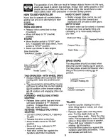
Page 9: ...before moving shift lever into another posi tion Tine movement is achieved by moving shift lever to either the counter rotating _ till position or the forward rotating _ till position and engaging drive con trol bar FORWARD WHEELS ONLY TINES STOPPED Release drive control bar and move shift lever indicator to F forward position Engage drive control bar and tiller will move forward REVERSE WHEELS ON...

Page 10: ... raised for deep tilling and lowered for shallow tilling to protect small plants from being buried Loosen nut A in slot and nut B Move shield to desired position both sides Retighten nuts TO TRANSPORT _CAUTION Before lifting or transport ing allow tiller engine and muffler to cool Disconnect spark plug wire Drain gasoline from fuel tank AROUND THE YARD Release the depth stake pin Move the depth st...

Page 11: ...position when starting engine When starting engine for the first time or if engine has run out of fuel it will take extra pulls of the recoil starter to move fuel from the tank to the engine Make sure spark plug wire is properly connected Move shift lever indicator to N neutral position Place throttle control in FAST position Turn fuel shut off valve 1 4 turn to OPEN position Move choke control to...

Page 12: ...g itself and you toward the row next to it Do not lean on handle This takes weight off the wheels and reduces traction To get through a really tough section of sod or hard ground apply upward pressure on handle or lower the depth stake 5 J CULTIVATING Cultivating is destroying the weeds between rows to prevent them from robbing nourishment and moisture from the plants At the same time breaking up ...

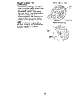
Page 13: ...hole in inner wheel hub lines up with inner hole in axle Replace clevis pin and hairpin clip on inside of wheel and remove blocks Repeat preceding steps on left hand side NOTE In extremely rough conditions and while cultivating the wheels should be moved outward on the axle for increased stability OUTER VIEW OF TIRE Clevis Pin Hairpin Cllip INNER VIEW OF TIRE Clevis Pin Hairpir 13 ...

Page 14: ...t maintain tiller as instructed in this manual Some adjustments will need to be made periodically to properly maintain your tiller All adjustments in the Service and Adjustments section of this manual should be checked at least once each season Once a year you should replace the spark plug clean or replace air filter and check tines and belts for wear A new spark plug and clean air filter assure p...

Page 15: ...hen warm Use a funnel to prevent oil spill on tiller and catch oil in a suitable container Remove oil drain plug Be careful not to allow dirt to enter the engine For easier removal of plug use 7 16 12 Pt socket with extension Tip tiller forward to drain oil After oil has drained completely replace oil drain plug and tighten securely Remove oil fill plug Refill engine with oil through oil fill tube...

Page 16: ...shown in PROD UCT SPECIFICATIONS on page 4 of this manual TRANSMISSION Once a season lubricate the right hand gear case grease fitting with 1 oz of EP 1 grease CLEANING Clean engine wheels finish etc of all foreign matter Keep finished surfaces and wheels free of all gasoline oil etc Protect painted surfaces with automo tive type wax We do not recommend using a garden hose to clean your unit unles...

Page 17: ...lip and Clevis Pin TO REPLACE GROUND DRIVE BELT Remove belt guard as described in TO REMOVE BELT GUARD Remove old belt by slipping off engine pulley first then remove from transmis sion pulley Place new belt in groove of transmis sion pulley and into engine pulley BELT MUST BE IN GROOVE ON TOP OF IDLER PULLEY NOTE POSITION OF BELT TO GUIDES Check belt adjustment as described below Replace belt gua...

Page 18: ... be checked for sharpness wear and bending particularly the tines which are next to the transmission If the gap between the tines exceeds 3 1 2 inches they should be replaced or straightened as necessary For tines that are slightly worn the bolted tine and hub assemblies caEbe switched between sides to continue till ing in the same tilling mode if tilling in a different mode is desired then the bo...

Page 19: ...amp screw Move throttle lever up until it touches high speed stop and hold in this position Tighten cable clamp screw securely F Clamp uel Tank _ Screw I and Wire Governor Control Lever TO ADJUST CARBURETOR The carburetor has been preset at the factory and adjustment should not be necessary However engine perfor mance can be affected by differences in fuel temperature altitude or load If the carbu...

Page 20: ...el tank Start the engine and let it run until the fuel lines and carburetor are empty Never use engine or carburetor cleaner products in the fuel tank or permanent damage may occur Use fresh fuel next season NOTE Fuel stabilizer is an acceptable alternative in minimizing the formation of fuel gum deposits during storage Add stabilizer to gasoline in fuel tank or storage container Always follow the...

Page 21: ... 4 Clean or replace air cleaner cartridge 5 Drain fuel tank and carbure tor and refill tank with fresh gasoline 6 Remove fuel tank and clean 7 Make sure spark plug wire is seat ed properly on plug 8 Replace spark plug or adjust gap 9 Make necessary adjustments 1 Place throttle control in FAST position 2 Clean or replace air cleaner cartridge 3 Replace spark plug or adjust gap 4 Drain fuel tank and...

Page 22: ...ode 1 Gears not timed 1 Shift lever set in between counter rotating till position and forward rotating till position 2 Tines jammed CORRECTION 1 Check oil level change oil 2 Clean engine air screen 3 Clean cylinder fins air screen muffler area 4 Remove and clean muffler 5 Adjust carburetor to richer position 1 Moisten ground or wait for more favorable soil conditions 2 Adjust depth stake 1 Wait fo...

Page 23: ... 2 1 2 Handle Grip Clip Hairpin Bolt Shoulder Handle Shift Grommet Rubber Rod Shift Bolt RBHD SQNI 3 8 16 x 1 Gr 5 Lock Handle Nut Crownlock 3 8 16 KEY PART NO NO DESCRIPTION 19 19131611 Washer 13 32 x 1 x 11 Ga 20 109228X Lever Lock Handle 21 150629 Handle Assemble 22 165197 Clip Plastic Cable 23 86777 Screw Hex Washer Hd Slotted 10 24 x 1 2 24 9484R Qip 25 73970500 Locknut Hex Flange 26 110675X ...

Page 24: ...Set 5 16 18 x 3 8 Spacer Split 327 x 42 x 2 09 Washer 11 32 x 11 16 x 16 Ga Sheave Transmission Ring Retainer Spacer Sp_it 327 x 42 x 1 22 Bolt Fin Hex 5 16 24 x 1 2 _m F_rn Tire Valve Rivet Ddlled KEY PART NO NO DESCRIPTION 25 STD624003 Clip Hairpin 26 165501X558 Guard Belt 27 132801 Belt V 28 104679X Pulley Idler 29 12000032 Ring Klip 30 159229 Bracket Idler 31 102384X Bolt Hex 5 16 16 x 12 32 1...

Page 25: ...er 11 32 x 11 16 x 16Ga Bolt Hex 5 16 18 x 3 4 Bracket Reinforcement Bolt Hex 5 16 18 x 2 Counter Weight R H Washer Lock 3 8 Nut Hex 3 8 16 Bolt Hex 5 16 18 x 1 1 2 Clip Hairpin Rivet Drilled KEY PART NO NO DESCRIPTION 13 102190X Tire 150750 Ri_ 795R Tire Valve 14 STD541431 Nut Keps 5 16 18 15 Engine See Breakdown Craftsman Model No 121402 0161 E 1 16 7192J Tie Cable STANDARDHARDWARE PURCHASELOCAL...

Page 26: ...00 Ring Klip 53 165140 Gear Assembly Reverse Idler 54 161528 Includes Key Nos 21 and 22 Gear Reverse Idler 55 3400R Bearing Needle 56 161529 Shaft Reverse Idler 57 165889 Washer Lock 7 16 58 17720412 Nut Hex 7 16 20 60 6855M Bearing Shaft Ground Drive LH 6066J Spacer 0 765 x 1 125 x 1 23 Chain 35 50 Pitch Ground Shaft Assembly Bearing Shaft Ground Drive R H Spacer 0 70 x 1 00 x 1 150 48 53 DESCRIP...

Page 27: ...140404 Bracket Latch 25 6712J Spring Depth Stake 26 109227X Shield Tine 27 163497X558 Bolt Carriage 5 16 18 x 1 Gr 5 28 120588X Washer Lock 5 16 29 104085X558 Nut Hex 5 16 18 30 73970500 Bolt Carriage 5 16 18 x 1 1 4 31 163498X417 Bracket Shield Tine 32 73220400 Shield Side Outer R H 33 STD551125 Nut Hex Flange 1 4 20 Nut Wing Forged 5 16 18 Bolt Carriage 1 4 20 x 1 1 4 Gr 5 DESCRIPTION Gdp Nut He...

Page 28: ... 7 STD551137 8 74610616 16 163499 DESCRIPTION Pin Shear Assembly Hub and Plate Nut Hex 3 8 24 Washer Lock 3 8 Bolt Hex 3 8 24 x 1 Tine Spade KEY PART NO NO DESCRIPTION 17 163500 Tine Cleaning 18 3146R Clip Hairpin STANDARD HARDWARE PURCHASELOCALLY NOTE All component dimensions given in U S inches 1 inch 25 4 mm 49 ...

Page 29: ... 15 167155 16 171078 172098 DESCRIPTION Decal Logo Decal Logo Decal Logo Decal Description Decal Caution Drive Control Decal Hand Placement Decal Shift Indicator Decal Tine Shield Counter Rotating Tines Decal Warning Rotating Tines Decal Tine Drag Stake Decal Tine Shield Warning Dom Decal Oper Lub Instructions Decal Tine Depth Stake Decal Engine Decal Engine Decal Rewind Manual Owner s Eng Span 50...

Page 30: ...GGS STRATTON MODEL NUMBER 121402 0161 E1 306 307 24 1113 j t 478 _ 22 4r REQUIRES SPECIALTOOLS TO INSTALL SEE REPAIR INSTRUCTION MANUAL I 1019 LABEL KIT I I 1058 OWNER S MANUAL 13 _ ___ 383 _ 337 1034 415 741 12 21 _ 20 _ 30 I 27 i _ 27 _ _ 51 ...

Page 31: ...321 ENGINE BRIGGS STRATTON MODEL NUMBER 121402 0161 E1 365 i1 110 97 m_i 708 _ 341 _ Ii_l i i o4 276 i_ _i 137 _ 127 104 163 i 51 637 _ 12_ _ 110 _ _ _ 1_ 358 GASKET SET I 967 i I 862 961 I li i _ II _ 8751 971A 163 I I 971 _ 52 ...

Page 32: ...GGS STRATTON MODEL NUMBER 121402 0161 E1 562 _ _ _ _ __ _ __ 505 _ _ _ _ __ 1138 _ r _ _ _ _ _ 615 i j i J 601 87AI 190 601 190A _ 267 _ 209A 265 281 _ 663 _ _ _ _ 209 _ _ 632 _ _ _ _ 334 _ji _ 356 __ _ _i _ _i I 677 836 _ j _ 832 836 883 _ 53 ...

Page 33: ...TILLER MODEL NUMBER 917 293321 ENGINE BRIGGS STRATTON MODEL NUMBER 121402 0161 E1 597 _ _ 456 _ 56 _i II j 55 363 I 1036 LABEL KIT EMISSIONS I 1033 VALVE OVERHAULKIT _ e68 i_ 1022 _ _ I _ 61 54 ...

Page 34: ... 40 93312 Valve Retainer 300 693593 45 690977 Valve Tappet 304 693621 46 693404 Camshaft 305 690960 51 692555_ O_lntake Gasket 2 Required 306 693610 55 691422 Rewind Starter Housing 307 94515 56 498144 Starter Pulley 332 94877 58 693449 Starter Rope 333 692605 60 281101 Starter Rope Grip 334 94731 65 94904 Screw Rewind Starter 337 491055 95 94098 Screw Throttle Valve 356 398808 97 693412 Throttle ...

Page 35: ...1026693517 677 94896 Screw Muffler Deflector 1029 225246 689 263073 Friction Spring 1033690034 692 262715 Detent Spring Choke 1034281621 708 691321 tWasher Sold in Kit Only 1036 695041 718 230192 Locating Pin 1044 692590 741 692565 Timing Gear 105095137 742 692564 Retaining Ring 1058273700 746 692566 Idler Gear 1113692577 798 692559 Screw Rocker Arm 1138 694255 832 693583 Muffler Guard 836 94896 S...

Page 36: ...57 ...

Page 37: ...58 ...

Page 38: ...59 ...

Page 39: ...r smanuals that you need to do it yourself call Sears PartsDirectSM 1 800 366 PART0 a m 11 p m CST 1 800 366 7278 7 days a week www sears com partsdirect Topurchase or inquireabout a Sears Service Agreement 1 800 827 6655 7 a m 5 p m CST Mon Sat Para pedir servicio de reparaci0n a domicilio y para ordenarpiezas con entrega a domicilio 1 888 SU HOGARsM 1 888 784 6427 AuCanada pour service en fran a...

Reviews: