background image

Summary of Contents for 917.299082

Page 1: ... engine which operates differently from previously built engines Before you start the engine read and understand this Owner s Manual IMPORTANT Read and follow all Safety Rules and Instructions before operating this equipment Sears Roebuck and Co Hoffman Estates IL 60179 Visit our Craftsman website www sears com craftsman U S A 428622 Rev 1 ...

Page 2: ...s product is in use in the united states This Warranty gives you specific legal rights and you may also have other rights which vary from state to state SEARS ROEBUCKAND CO D 817WA HOFFMAN ESTATES IL 60179 U S A IMPORTANT This cutting machine is capable of amputating hands and feet and throw ing objects Failure to observe the following safety instructions could result in serious injury or death TR...

Page 3: ...children and pets away Do not overload the machine capacity by attempting to till too deep at too fast a rate Never operate the machine at high speeds on slippery surfaces Look be hind and use care when backing Never allow bystanders near the unit Use only attachments and accessories approved by the manufacturer of the tiller Never operate the tiller without good vis ibility or light Be careful wh...

Page 4: ...ornia Public Resources Code Other states may have similar laws Federal laws apply on federal lands A spark ar rester for the muffler is available through your nearest Sears service center See REPAIR PARTS section of this manual REPAIR PROTECTION AGREEMENTS Congratulations on making a smart pur chase Your new Craftsman product is designed and manufactured for years of dependable operation But like ...

Page 5: ...er of your tiller ENGINE SPARK PLUG MUFFLER AiR FILTER GAS CAN ENGINE OiL STABiLiZER TILLER PERFORMANCE FURROW OPENER TILLER MAINTENANCE BELT TINES SHEAR PiN O i 1 HAiRPiN CLIP CONTENTS OF HARDWARE PACK 2 Handle Locks 1 Carriage Bolt 3 8 16 UNC x 1 Gr 5 1 Hairpin Clips o 2 Shear Pins Clips G 1 Center Locknut 3 8 16 UNC 1 Cable Clip 1 Flat Washer 13 32xlx11Ga 0 1 Handle Lock Lever D 1 Pivot Bolt 3 ...

Page 6: ...ing material IMPORTANT When unpacking and as sembling tiller be careful not to stretch or kink cables 1 While holding handle assembly cut came ties securing handle assembly to top frame Let handle assembly rest on tiller 2 Remove top frame of carton 3 Slowly ease handle assembly up and place on top of carton 4 Cut down right hand front and right hand rear corners of carton Lay side carton wall dow...

Page 7: ...ll make it easier to remove tiller from carton Flat Washer Handle Lock Handle Lock Lever N Rear Cartridge Slot Bolt Handle Base Locknut_ Pivot Bolt INSERT CABLE CLIP Insert plastic cable clip into hole on the back of handle column Push cables into clip Handle Column Cable CONNECT SHIFT ROD 1 Insert end of shift rod into hole of shift lever indicator 2 Insert hairpin clip through hole of shift rod ...

Page 8: ...Control Shift Lever Indicator Throttle Control Drag Stake Depth Stake Leveling Shield Outer Side Shield Recoil Starter Handle MEETS ANSI SAFETY REQUIREMENTS Our tillers conform to the safety standards of the American National Standards Institute DEPTH STAKE Controls depth at which tiller will dig DRAG STAKE Controls forward speed in forward rotating till position DRIVE CONTROL BAR Used to engage t...

Page 9: ...ol bar before moving shift lever into another position Tine movement is achieved by moving shift lever to either the counter rotating _ till position or the forward rotating _ till position and engaging drive con trol bar FORWARD WHEELS ONLY TINES STOPPED The drag stake should be raised when tilling the counter rotating _ till position The drag stake should be lowered when tilling in the forward r...

Page 10: ...otating tine drive OUTER SIDE SHIELDS The back edges of the outer side shields are slotted so that the shields can be raised for deep tilling and lowered for shallow tilling to protect small plants from being buried 1 Loosen nut _ in slot and nut B 2 Move shield to desired position both sides 3 Retighten nuts TO TRANSPORT AI _CAUTION Before lifting or transporting allow tiller engine and muffler t...

Page 11: ...resh fuel next season See Storage Instructions for additional information Never use engine or carburetor cleaner products in the fuel tank or permanent damage may occur TO START ENGINE _ CAUTION Keep drive control bar in DISENGAGED position when starting engine When starting engine for the first time or if engine has run out of fuel it will take extra pulls of the recoil starter to move fuel from ...

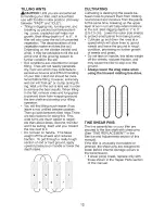
Page 12: ...re much easier to negoti ate than about faces Second the tiller won t be pulling itself and you toward the row next to it Do not lean on handle This takes weight off the wheels and reduces traction To get through a really tough section of sod or hard ground apply upward pressure on handle or lower the depth stake CULTIVATING Cultivating is destroying the weeds be tween rows to prevent them from ro...

Page 13: ...hole in inner wheel hub lines up with inner hole in axle 3 Replace clevis pin and hairpin clip on inside of wheel and remove blocks 4 Repeat preceding steps on left hand side NOTE In extremely rough conditions and while cultivating the wheels should be moved outward on the axle for increased stability Clevis Pin OUTER VIEW OF TIRE Hairpin Cllip INNER VIEW OF TIRE Hairpin Clip tire 2 13 ...

Page 14: ...y the operator must maintain tiller as instructed in this manual Some adjustments will need to be made periodically to properly maintain your tiller At least once a season check to see if you should make any of the adjustments described in the Service and Adjustments section of this manual Once a year you should replace the spark plug clean or replace air filter and check tines and belts for wear ...

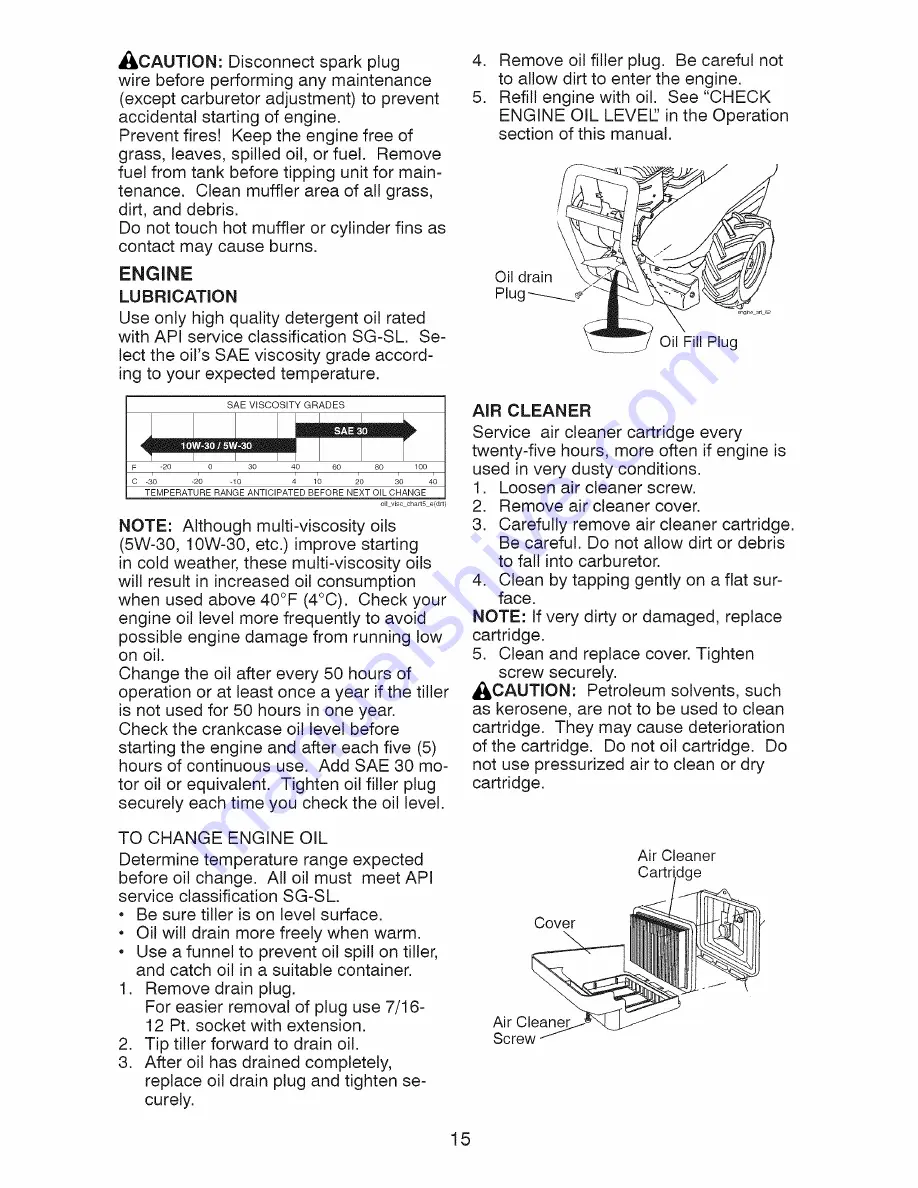
Page 15: ...AE 30 mo tor oil or equivalent Tighten oil filler plug securely each time you check the oil level TO CHANGE ENGINE OIL Determine temperature range expected before oil change All oil must meet API service classification SG SL Be sure tiller is on level surface Oil will drain more freely when warm Use a funnel to prevent oil spill on tiller and catch oil in a suitable container 1 Remove drain plug F...

Page 16: ...he right hand gear case grease fitting with 1 oz of EP 1 grease CLEANING Do not clean your tiller when the engine and transmission are hot We do not rec ommend using pressurized water garden hose etc to clean your unit unless the gasket area around the transmission and the engine muffler air filter and carburetor are covered to keep water out Water in engine will shorten the useful life of your ti...

Page 17: ...ocated Behind Screws Hairpin Clip and Clevis Pin TO 1 REPLACE GROUND DRIVE BELT Remove belt guard as described in TO REMOVE BELT GUARD 2 Remove old belt by slipping off engine pulley first then remove from trans mission pulley 3 Place new belt in groove of trans mission pulley and into engine pulley BELT MUST BE IN GROOVE ON TOP OF IDLER PULLEY NOTE POSITION OF BELT TO GUIDES 4 Check belt adjustme...

Page 18: ...ines should be checked for sharpness wear and bending particularly the tines which are next to the transmission If the gap between the tines exceeds 3 1 2 inches they should be replaced or straightened as necessary For tines that are slightly worn the bolted tine and hub assemblies can be switched between sides to continue tilling in the same tilling mode if tilling in a different mode is desired ...

Page 19: ... need adjustment see engine manual High speed stop is factory adjusted Do not adjust or damage may result IMPORTANT Never tamper with the engine governor which is factory set for proper engine speed overspeeding the engine above the factory high speed setting can be dangerous If you think the engine governed high speed needs adjusting contact your nearest authorized service center department which...

Page 20: ...g the en gine and letting it run until the fuel lines and carburetor are empty Never use engine or carburetor cleaner products in the fuel tank or permanent damage may occur Use fresh fuel next season NOTE Fuel stabilizer is an acceptable alternative in minimizing the formation of fuel gum deposits during storage Add stabilizer to gasoline in fuel tank or stop age container Always follow the mix r...

Page 21: ...everal minutes before attempting to start 4 Clean or replace air cleaner cartridge 5 Empty fuel tank and carbure tor and refill tank with fresh gasoline 6 Remove fuel tank and clean 7 Make sure spark plug wire is seat ed properly on plug 8 Replace spark plug or adjust gap 9 Make necessary adjust ments 1 Place throttle control in FAST position 2 Clean or replace air cleaner cartridge 3 Replace spar...

Page 22: ...tating till position 2 Tines jammed 1 Check oil level change oil 2 Clean engine air screen 3 Clean cylinder fins air screen muffler area 4 Remove and clean muffler 5 Adjust carburetor to richer position 1 Moisten ground or wait for more favorable soil condi tions 2 Adjust depth stake Wait for more favorable soil conditions 1 Engagetine control 2 Inspect adjust V belt 3 Inspect V belt 1 Set depth s...

Page 23: ...servan las instrucciones de seguridad siguientes se pueden producir lesiones graves o la muerte ENTRENAMIENTO Lea el Manual del Dueflo cuidadosamente Familiaricese completamente con los controles y con el uso adecuado del equipo Sepa c6mo parar la unidad y desenganchar los controles rapidamente Nunca permita que los niflos operen el equi po Nunca permita que los adultos operen el equipo sin los co...

Page 24: ...luz Tenga cuidado alcultivarenterrenoduro Losbrazospueden quedarse agarrados en elsueloe impulsar alacultivadora hacia adelante Siestosucede sueltelosmangos y norestrinja lam quina MANTENIMIENTO Y ALMACENAIVIIENTO Mantenga los accesorios y aditamentos de la m quina en buenas condiciones para el funcionamiento Revise las clavijas de seguro los pernos de montaje del motor y otros pernos a intervalos...

Page 25: ...lenciador Vea la secci6n de Partes de Repuesto en el manual Ingles del dueSo ACUERDOS DE PROTECCK_N PARA LA REPARACI6N Congratulaciones per su buena compra Su nuevo producto Craftsman est diseSado y fabricado para funcionar de mode fiable per muchos aSos Pero come todos los productos puede necesitar alguna reparaci6n de tanto en tanto En este case tenet un Acuerdo de Protecci6n para la Reparaci6n ...

Page 26: ...OR FILTRO DE AmRE LATA DE GASOLINA ACEITE DEL MOTOR ESTABtLIZADOR RENDIMIENTO DE LA CULTIVADORA ABRIDOR DE SURCOS MANTENIMIENTO DE LA CULTIVADORA CORREA BRAZOS CLAVIJA DE SEGURO ABRAZADERA DE HORQUILLA CONTENIDO DEL CONJUNTO DE FERRETERIA 2 Cierres del mango 1 Abrazaderas de horquilla l 2 Clavijade seguro retencion 1 Perno portadores 3 8 16 UNC x 1 clase 5 1 Arandela plana 13 32xlx11Ga Q 1 Tuerca ...

Page 27: ...ultivadora tenga cuidado de no estirar o enredar los cables 1 AI mismo tiempo que se sujeta el conjunto del mango corte las ligaduras del cable que aseguran el conjunto del mango al bastidor superior y a la estaca de profundidad Per mita que el conjunto del mango descanse en la cultivadora 2 Remueva el bastidor superior de la caja de cart6n 3 Lentamente saque el conjunto de mango hacia arriba y p6...

Page 28: ...ja de Cambio Perno portador trasero Base del Mango Bouton de _ _ pivot Tuercas de Seguridad INSERClON DE LA ABRAZADERA DEL CABLE Inserte la abrazadera del cable de pl stico dentro del agujero en la parte trasera de la columna del mango Empuje los cables dentro de la abrazadera Cotumna det Mango Cable Abrazadera del Cable handles 101 CONEXION DE LA VARILLA DE CAMBIO 1 Inserte el extremo de la varil...

Page 29: ...trol de la aceleraci6n Estaca de Estaca de Arrastre Defensa de nivelaci6n Defensa lateral exterior Mango del arrancador de cutateo Nuestras cultivadoras cumplen con los est ndares de seguridad del American National Standards Institute BARRA DE CONTROL DE LA IMPULSION Se usa para enganchar los brazos CONTROL DE LA ACELERACION Controla la velocidad del motor DEFENSA DE NIVELACION Nivela el suelo lab...

Page 30: ...PULSION DE RUEDAS Siempre suelte la barra de control de la im pulsi6n antes de mover la palanca de cambio a otra posici6n El movimiento de los dientes se Iogra al mover la palanca de cambio cualquiera de la contra rotaci6n _ posici6n para segar y en ganchando la barra de control de mando _ posici6n para segar o la posici6n de rotaci6n hacia delante MARCHA HACIA ADELANTE RUEDAS SO LAMENTE BRAZOS PA...

Page 31: ...otaci6n hacia adelante DEFENSAS LATERALES EXTERIORES Los bordes trasero de las defensas laterales exteriores son rasurados de modo que estas se puedan levantar para hacer un labrado profundo y bajar para uno poco profundo para evitar enterrar las plantas peque_as 1 Suelte latuerca _ en la ranuray latuerca B 2 Mueva la defensa a la posici6n deseada en ambos lados 3 Vuelva a apretar las tuercas PARA...

Page 32: ...ucciones para el Almacenamiento para m s informaci6n Nunca use productos de limpieza para el motor o para el carburador en el estanque del combustible pues se pueden producir dahos permanentes PARA HACER ARRANCAR EL MOTOR _kPRECAUCl6N Mantenga la barra de control de la impulsi6n en la posici6n DESEN GANCHADO cuando haga arrancar el motor Cuando este empezando un motor por la primera vez o si el mo...

Page 33: ... CULTIVO El cultivo quiere decir la destrucci6n de las malezas entre las hileras para evitar que estas le roben la nutrici6n y la humedad alas plantas AI mismo tiempo si se rompe la capa superior de la costra del suelo este puede retener la humedad La mejor profundidad de excavaci6n es de 1 a 3 Baje las defensas laterales exteri ores para evitar enterrar las plantas pequeflas Cultive hacia arriba ...

Page 34: ...or se alinee con el agujero interior en el eje 3 Vuelva a colocar la clavija de horquilla y la abrazadera de horquilla en la parte interior de la rueda y remueva los bloques 4 Repita los pasos anteriores para el lado izquierdo AVlSO En condiciones muy dificiles cuando se cultiva las ruedas tienen que moverse hacia afuera en el eje para aumentar la estabilidad VISTA EXTERIOR DE LA LLANTA Olavija de...

Page 35: ... instrucciones descritas en este manual Hay algunos ajustes que se tienen que hacer en forma peri6dica para poder mantener su cultivadora adecuadamente Todos los ajustes en la secci6n de Servicio y Ajustes de este manual tienen que ser revisados por Io menos una vez por cada temporada Una vez al aSo cambie la bujia Iimpie o cambie el filtro de aire y revise si los brazos y las correas est n desgas...

Page 36: ...0 horas de oper aci6n o per Io menos una vez al aflo si el tiller se utiliza menos 50 horas el aflo Revise el nivel del aceite del carter antes de hacer arrancar el motor y despues de cada cinco 5 horas de use continuado Agregue aceite de motor SAE 30 o su equivalente Apriete el tap6n del dep6sito de relleno del aceite en forma segura cada vez que revise el nivel del aceite PARA CAMBIAR EL ACEITE ...

Page 37: ... lado derecho della caja de velocidades con 1 onza de grasa EP 1 LIMPIEZA No limpie su cultivadora cuando el motor y la transmisi6n esten calientes No recomendamos el uso de agua presurizada manguera del jardin etc para limpiar su unidad a menos que el rea de la junta alrededor de la transmisi6n y del silenciador del motor del filtro de aire y del carburador se cubran ara protejerlos del agua El a...

Page 38: ... clavija de horquitla PARA CAMBIAR LA CORREA DE IMPUL SION DE RECORRIDO 1 Remueva la protecci6n de la correa segOn se ha descrito en PARA REMOVER LA PROTECCION DE LA CORREA 2 Remueva la correa antigua desliz ndola fuera de la polea del motor primero y rem ueva la polea de la transmisi6n 3 Ponga la correa nueva en la ranura de la polea de la transmisi6n y dentro de la polea del motor LA CORREA TIEN...

Page 39: ...ficar si est n afilados desgastados o doblados especialmente los que se encuentran al lado de la transmisi6n Si el espacio libre entre los brazos es m s de 3 1 2 pulgadas se tienen que cambiar o enderezar segQn sea necesario Para aquellos dientes los cuales esta un poco usados dientes sujetados con tornillos o conjuntos del eje pueden set intercambia dos entre ambos lados para continuar con el mis...

Page 40: ...e de alta velocidad ha sido ajustado en la f brica No Io ajuste se pueden producir dahos IMPORTANTE Nunca manipule el regulador del motor el que ha sido ajusta do en la fabrica para la velocidad del motor adecuada puede set peligroso hacer funcionar el motor a una velocidad por sobre elajuste de lata velocidad de la fabrica Si cree que la velocidad alta regulada del motor necesita ajuste p6ngase e...

Page 41: ...o en marcha el motor y dejandolo funcionar hasta que el carburante termine el carbura dor este vacio Nunca use los productos para limpieza del carburador o del motor en el estanque de combustible pues se pueden producir dahos permanentes Use combustible nuevo la pr6xima tempo rada AVlSO El estabilizador de combustible es una alternativa aceptable para reducir a un minimo la formaci6n de dep6sitos ...

Page 42: ...aciar el estanque de combustible y el carburador vuelva a Ilenar el estanque con gasolina nueva 6 Remueva el estanque de com bustible y limpielo 7 AsegOrese que el alambre de la bujia este asentado en forma adecuada en esta 8 Cambie la bujia o ajuste la abertura 9 Haga los ajustes necesarios 1 Ponga el control de la aceleraci6n en la posici6n de RAPIDO FAST 2 Limpie o cambie el cartucho del filtro...

Page 43: ...ltivo 1 Las transmisiones no est_ n distribuidas 1 El conjunto de palanca esta colocado entre la posici6n para segarde contra rotaci6n y la posici6n para segar hacia adelante 2 Los dientes est_ n atascados CORRECCION 1 Revise el nivel del aceite cambie el aceite 2 Limpie la rejilla de aire del motor 3 Limpie las aletas del cilindro la rejilla de aire y el area del silenciador 4 Remueva y limpie el...

Page 44: ...8 x 2 1 2 Handle Grip Retainer Spring Bolt Shoulder Handle Shift Grommet Rubber Rod Shift Bolt Rdhd Sqnk 3 8 16 x 1 Gr 5 Lock Handle KEY PART NO NO DESCRIPTION 18 STD541437 Nut Crowntock 3 8 16 19 19131611 Washer 13 32xlx11 Ga 20 109228X Lever Lock Handle 21 420524 Handle Assemble 22 165197 Clip Plastic Cable 23 86777 Screw Hex Washer Hd Slotted 10 24 x 1 2 24 9484R Clip 25 73970500 Locknut Hex Fl...

Page 45: ...a Sheave Transmission Ring Retainer Spacer Split 327 x 42 x 1 220 Bolt Fin Hex 5 16 24 x 1 2 Tire Rim Tire Valve Rivet Drilled Retainer Spring Guard Belt KEY PART NO NO DESCRIPTION 27 132801 Belt V 28 104679X Pulley Idler 29 12000032 Ring Klip 30 159229 Bracket Idler 31 102384X Bolt Hex 5 16 16 x 12 32 102141X Shaft Idter Arm 33 STD523710 Bolt Hex 3 8 16 x 1 34 102383X Counterweight LH 36 102331X ...

Page 46: ...Bumper Locknut Hex Flange 5 16 18 Washer 11 32x11 16x16Ga Bolt Hex 5 16 18 x 3 4 Bracket Reinforcement RH Counter Weight R H Bolt Hex 5 16 18 x 1 1 2 Retainer Spring Rivet Drilled Tire Rim Tire Valve KEY PART NO NO 15 22 74760528 44 73510600 DESCRIPTION Engine See Breakdown Briggs Stratton Model No 121002 0220 B8 Bolt Fin Hex 5 16 18 uric x 1 3 4 Nut Keps Hex 3 8 16 uric NOTE All component dimensi...

Page 47: ...ift 50 106147X Washer 51 17720408 Ring Klip 52 73220500 Gear Assembly Reverse Idler 53 165140 Includes Key Nos 21 and 22 54 161528 Gear Reverse Idler Bearing Needle 55 3400R Shaft Reverse Idler 56 161529 Washer Lock 7 16 57 165889 Nut Hex 7 16 20 58 179520 Bearing Shaft Ground Drive L H 60 183226 Spacer 0 765 x 1 125 x 1 23 6066J Chain 35 50 Pitch Ground Shaft Assembly Bearing Shaft Ground Drive R...

Page 48: ...24343X Bracket Shield Tine 32 15 161414X428 Shield Side Outer R H 33 16 73900400 Nut Hex Flange 1 4 20 38 17 162175 Nut Wing Forged 5 16 18 18 STD532512 Bolt Carriage 1 4 20 x 1 1 4 Gr 5 19 102701X Grip 20 STD541037 Nut Hex 3 8 16 21 102156X Stake Depth PART NO DESCRIPTION 74930632 Bolt Hex 3 8 16 x 2 4440J Hinge 72140404 Bolt Carriage 1 4 20 x 1 2 6712J Cap Vinyl 109227X Pad Idler 102695X428 Shie...

Page 49: ... 132673 3146R 188845 73610600 STD551137 DESCRIPTION Pin Shear Clip Hairpin Tine Assembly Nut Hex 3 8 24 Washer Lock 3 8 KEY PART NO NO DESCRIPTION 8 74610616 Bolt Hex 3 8 24 x 1 16 163499 Tine Spade 17 163500 Tine Cleaning NOTE All component dimensions given in U S inches 1 inch 25 4 mm 49 ...

Page 50: ... 166188 Decal 9 177568 Decal 10 418559 Decal 11 409143 Decal 12 409145 Decal 13 418558 Decal 14 419743 Decal 15 411816 Decal 428622 DESCRIPTION Console Logo Belt Guard Tine Shield Caution Drive Control Hand Placement Shift Indicator Tine Shield Dual Rotating Tines Warning DRT Tine Shield DRT FOR Tank AC Tine Shield Rev Console Control Rewind Manual Owner s English Spanish 50 ...

Page 51: ...TILLER MODEL NUMBER 917 299082 ENGINE BRIGGS STRATTON MODEL NUMBER 121002 0220 B8 968 535 836 832 300 613 883 445 1211 23 1005 1070_ I 1036 EMISSIONS LABEL I 1210 456 689 _ 51 ...

Page 52: ...20 B8 958 190_ _ 358 ENGINE GASKET SET 20 163 _ _ 1O22 868 _ 993 51 883_ 957 1270 163 lO9 _y I 633 _ 692 _ _o_ _ _ d _ _ b 1 _ p 2 95 _ s _ _ 186 51 334 365_ 1095 VALVE GASKET SET 9 c 0 1022 104 _ 121 CARBURETOR OVERHAUL KIT 127 _ 633 633A 3331 fS _ 562 _ _ b 356 _z 281 209A 52 ...

Page 53: ...TON MODEL NUMBER 121002 0220 B8 306 307 _ 742 746 415 12 I 1329 REPLACEMENT ENGINE I I 48 SHORT BLOCK 1330 REPAIR MANUAL I I 1058OPERATOR S MANUAL I 1026 O22 15A 24 914 _ _ 914A_ 914B_ 332 _ 146 741 45 1026 _ C 238 36 O _ 4o_ L _ 1022 619_ 1034 1029 53 ...

Page 54: ... Pawl Friction 35 691304 Spring Valve intake 459 281505s PawI Ratchet 36 691304 Spring Valve Exhaust 505 691251 Nut Governor Control Lever 37 699661 Guard Flywheel 535 493537s Filter Air Cleaner Foam 40 692194 Retainer Valve 552 692346 Bushing Governor Crank 45 690977 Tappet Valve 562 691119 Bolt Governor Control Lever 46 693404 Camshaft 597 691696 Screw Pawl Friction Plate 48 699582 Short Block 6...

Page 55: ...ocker Cover Top Screw Rocker Cover Side Cap Fuel Tank Valve Fuel Shut Off Cover Air Cleaner Tank Fuel Bowl Fuel Gasket Cylinder Head Plate Fan Flywheel Gasket Rocker Cover Cover Rocker Rod Push Arm Rocker Guide Push Rod Label Emissions AvailableFrom A Briggs Stratton Authorized Dealer 277040 Operator s Manual 699201 Screw Flywheel Fan 791798 Gasket Set Valve 791849 Pulley Spring Assembly Pulley 79...

Page 56: ...me day or night 1 800 469 4663 U S A and Canada www sears com www sears ca Our Home For repair of carry in products like vacuums lawn equipment and electronics call or go on line for the nearest Sears Parts and Repair Center 1 800 488 1222 Anytime day or night U S A only www sears com To purchase a protection agreement U S A or maintenance agreement Canada on a product serviced by Sears 1 800 827 ...

Page 57: ... engine which operates differently from previously built engines Before you start the engine read and understand this Owner s Manual IMPORTANT Read and follow all Safety Rules and Instructions before operating this equipment Sears Roebuck and Co Hoffman Estates IL 60179 Visit our Craftsman website www sears com craftsman U S A 428622 Rev 1 ...

Page 58: ...s product is in use in the united states This Warranty gives you specific legal rights and you may also have other rights which vary from state to state SEARS ROEBUCKAND CO D 817WA HOFFMAN ESTATES IL 60179 U S A IMPORTANT This cutting machine is capable of amputating hands and feet and throw ing objects Failure to observe the following safety instructions could result in serious injury or death TR...

Page 59: ...children and pets away Do not overload the machine capacity by attempting to till too deep at too fast a rate Never operate the machine at high speeds on slippery surfaces Look be hind and use care when backing Never allow bystanders near the unit Use only attachments and accessories approved by the manufacturer of the tiller Never operate the tiller without good vis ibility or light Be careful wh...

Page 60: ...ornia Public Resources Code Other states may have similar laws Federal laws apply on federal lands A spark ar rester for the muffler is available through your nearest Sears service center See REPAIR PARTS section of this manual REPAIR PROTECTION AGREEMENTS Congratulations on making a smart pur chase Your new Craftsman product is designed and manufactured for years of dependable operation But like ...

Page 61: ...er of your tiller ENGINE SPARK PLUG MUFFLER AiR FILTER GAS CAN ENGINE OiL STABiLiZER TILLER PERFORMANCE FURROW OPENER TILLER MAINTENANCE BELT TINES SHEAR PiN O i 1 HAiRPiN CLIP CONTENTS OF HARDWARE PACK 2 Handle Locks 1 Carriage Bolt 3 8 16 UNC x 1 Gr 5 1 Hairpin Clips o 2 Shear Pins Clips G 1 Center Locknut 3 8 16 UNC 1 Cable Clip 1 Flat Washer 13 32xlx11Ga 0 1 Handle Lock Lever D 1 Pivot Bolt 3 ...

Page 62: ...ing material IMPORTANT When unpacking and as sembling tiller be careful not to stretch or kink cables 1 While holding handle assembly cut came ties securing handle assembly to top frame Let handle assembly rest on tiller 2 Remove top frame of carton 3 Slowly ease handle assembly up and place on top of carton 4 Cut down right hand front and right hand rear corners of carton Lay side carton wall dow...

Page 63: ...ll make it easier to remove tiller from carton Flat Washer Handle Lock Handle Lock Lever N Rear Cartridge Slot Bolt Handle Base Locknut_ Pivot Bolt INSERT CABLE CLIP Insert plastic cable clip into hole on the back of handle column Push cables into clip Handle Column Cable CONNECT SHIFT ROD 1 Insert end of shift rod into hole of shift lever indicator 2 Insert hairpin clip through hole of shift rod ...

Page 64: ...Control Shift Lever Indicator Throttle Control Drag Stake Depth Stake Leveling Shield Outer Side Shield Recoil Starter Handle MEETS ANSI SAFETY REQUIREMENTS Our tillers conform to the safety standards of the American National Standards Institute DEPTH STAKE Controls depth at which tiller will dig DRAG STAKE Controls forward speed in forward rotating till position DRIVE CONTROL BAR Used to engage t...

Page 65: ...ol bar before moving shift lever into another position Tine movement is achieved by moving shift lever to either the counter rotating _ till position or the forward rotating _ till position and engaging drive con trol bar FORWARD WHEELS ONLY TINES STOPPED The drag stake should be raised when tilling the counter rotating _ till position The drag stake should be lowered when tilling in the forward r...

Page 66: ...otating tine drive OUTER SIDE SHIELDS The back edges of the outer side shields are slotted so that the shields can be raised for deep tilling and lowered for shallow tilling to protect small plants from being buried 1 Loosen nut _ in slot and nut B 2 Move shield to desired position both sides 3 Retighten nuts TO TRANSPORT AI _CAUTION Before lifting or transporting allow tiller engine and muffler t...

Page 67: ...resh fuel next season See Storage Instructions for additional information Never use engine or carburetor cleaner products in the fuel tank or permanent damage may occur TO START ENGINE _ CAUTION Keep drive control bar in DISENGAGED position when starting engine When starting engine for the first time or if engine has run out of fuel it will take extra pulls of the recoil starter to move fuel from ...

Page 68: ...re much easier to negoti ate than about faces Second the tiller won t be pulling itself and you toward the row next to it Do not lean on handle This takes weight off the wheels and reduces traction To get through a really tough section of sod or hard ground apply upward pressure on handle or lower the depth stake CULTIVATING Cultivating is destroying the weeds be tween rows to prevent them from ro...

Page 69: ...hole in inner wheel hub lines up with inner hole in axle 3 Replace clevis pin and hairpin clip on inside of wheel and remove blocks 4 Repeat preceding steps on left hand side NOTE In extremely rough conditions and while cultivating the wheels should be moved outward on the axle for increased stability Clevis Pin OUTER VIEW OF TIRE Hairpin Cllip INNER VIEW OF TIRE Hairpin Clip tire 2 13 ...

Page 70: ...y the operator must maintain tiller as instructed in this manual Some adjustments will need to be made periodically to properly maintain your tiller At least once a season check to see if you should make any of the adjustments described in the Service and Adjustments section of this manual Once a year you should replace the spark plug clean or replace air filter and check tines and belts for wear ...

Page 71: ...AE 30 mo tor oil or equivalent Tighten oil filler plug securely each time you check the oil level TO CHANGE ENGINE OIL Determine temperature range expected before oil change All oil must meet API service classification SG SL Be sure tiller is on level surface Oil will drain more freely when warm Use a funnel to prevent oil spill on tiller and catch oil in a suitable container 1 Remove drain plug F...

Page 72: ...he right hand gear case grease fitting with 1 oz of EP 1 grease CLEANING Do not clean your tiller when the engine and transmission are hot We do not rec ommend using pressurized water garden hose etc to clean your unit unless the gasket area around the transmission and the engine muffler air filter and carburetor are covered to keep water out Water in engine will shorten the useful life of your ti...

Page 73: ...ocated Behind Screws Hairpin Clip and Clevis Pin TO 1 REPLACE GROUND DRIVE BELT Remove belt guard as described in TO REMOVE BELT GUARD 2 Remove old belt by slipping off engine pulley first then remove from trans mission pulley 3 Place new belt in groove of trans mission pulley and into engine pulley BELT MUST BE IN GROOVE ON TOP OF IDLER PULLEY NOTE POSITION OF BELT TO GUIDES 4 Check belt adjustme...

Page 74: ...ines should be checked for sharpness wear and bending particularly the tines which are next to the transmission If the gap between the tines exceeds 3 1 2 inches they should be replaced or straightened as necessary For tines that are slightly worn the bolted tine and hub assemblies can be switched between sides to continue tilling in the same tilling mode if tilling in a different mode is desired ...

Page 75: ... need adjustment see engine manual High speed stop is factory adjusted Do not adjust or damage may result IMPORTANT Never tamper with the engine governor which is factory set for proper engine speed overspeeding the engine above the factory high speed setting can be dangerous If you think the engine governed high speed needs adjusting contact your nearest authorized service center department which...

Page 76: ...g the en gine and letting it run until the fuel lines and carburetor are empty Never use engine or carburetor cleaner products in the fuel tank or permanent damage may occur Use fresh fuel next season NOTE Fuel stabilizer is an acceptable alternative in minimizing the formation of fuel gum deposits during storage Add stabilizer to gasoline in fuel tank or stop age container Always follow the mix r...

Page 77: ...everal minutes before attempting to start 4 Clean or replace air cleaner cartridge 5 Empty fuel tank and carbure tor and refill tank with fresh gasoline 6 Remove fuel tank and clean 7 Make sure spark plug wire is seat ed properly on plug 8 Replace spark plug or adjust gap 9 Make necessary adjust ments 1 Place throttle control in FAST position 2 Clean or replace air cleaner cartridge 3 Replace spar...

Page 78: ...tating till position 2 Tines jammed 1 Check oil level change oil 2 Clean engine air screen 3 Clean cylinder fins air screen muffler area 4 Remove and clean muffler 5 Adjust carburetor to richer position 1 Moisten ground or wait for more favorable soil condi tions 2 Adjust depth stake Wait for more favorable soil conditions 1 Engagetine control 2 Inspect adjust V belt 3 Inspect V belt 1 Set depth s...

Page 79: ...servan las instrucciones de seguridad siguientes se pueden producir lesiones graves o la muerte ENTRENAMIENTO Lea el Manual del Dueflo cuidadosamente Familiaricese completamente con los controles y con el uso adecuado del equipo Sepa c6mo parar la unidad y desenganchar los controles rapidamente Nunca permita que los niflos operen el equi po Nunca permita que los adultos operen el equipo sin los co...

Page 80: ...luz Tenga cuidado alcultivarenterrenoduro Losbrazospueden quedarse agarrados en elsueloe impulsar alacultivadora hacia adelante Siestosucede sueltelosmangos y norestrinja lam quina MANTENIMIENTO Y ALMACENAIVIIENTO Mantenga los accesorios y aditamentos de la m quina en buenas condiciones para el funcionamiento Revise las clavijas de seguro los pernos de montaje del motor y otros pernos a intervalos...

Page 81: ...lenciador Vea la secci6n de Partes de Repuesto en el manual Ingles del dueSo ACUERDOS DE PROTECCK_N PARA LA REPARACI6N Congratulaciones per su buena compra Su nuevo producto Craftsman est diseSado y fabricado para funcionar de mode fiable per muchos aSos Pero come todos los productos puede necesitar alguna reparaci6n de tanto en tanto En este case tenet un Acuerdo de Protecci6n para la Reparaci6n ...

Page 82: ...OR FILTRO DE AmRE LATA DE GASOLINA ACEITE DEL MOTOR ESTABtLIZADOR RENDIMIENTO DE LA CULTIVADORA ABRIDOR DE SURCOS MANTENIMIENTO DE LA CULTIVADORA CORREA BRAZOS CLAVIJA DE SEGURO ABRAZADERA DE HORQUILLA CONTENIDO DEL CONJUNTO DE FERRETERIA 2 Cierres del mango 1 Abrazaderas de horquilla l 2 Clavijade seguro retencion 1 Perno portadores 3 8 16 UNC x 1 clase 5 1 Arandela plana 13 32xlx11Ga Q 1 Tuerca ...

Page 83: ...ultivadora tenga cuidado de no estirar o enredar los cables 1 AI mismo tiempo que se sujeta el conjunto del mango corte las ligaduras del cable que aseguran el conjunto del mango al bastidor superior y a la estaca de profundidad Per mita que el conjunto del mango descanse en la cultivadora 2 Remueva el bastidor superior de la caja de cart6n 3 Lentamente saque el conjunto de mango hacia arriba y p6...

Page 84: ...ja de Cambio Perno portador trasero Base del Mango Bouton de _ _ pivot Tuercas de Seguridad INSERClON DE LA ABRAZADERA DEL CABLE Inserte la abrazadera del cable de pl stico dentro del agujero en la parte trasera de la columna del mango Empuje los cables dentro de la abrazadera Cotumna det Mango Cable Abrazadera del Cable handles 101 CONEXION DE LA VARILLA DE CAMBIO 1 Inserte el extremo de la varil...

Page 85: ...trol de la aceleraci6n Estaca de Estaca de Arrastre Defensa de nivelaci6n Defensa lateral exterior Mango del arrancador de cutateo Nuestras cultivadoras cumplen con los est ndares de seguridad del American National Standards Institute BARRA DE CONTROL DE LA IMPULSION Se usa para enganchar los brazos CONTROL DE LA ACELERACION Controla la velocidad del motor DEFENSA DE NIVELACION Nivela el suelo lab...

Page 86: ...PULSION DE RUEDAS Siempre suelte la barra de control de la im pulsi6n antes de mover la palanca de cambio a otra posici6n El movimiento de los dientes se Iogra al mover la palanca de cambio cualquiera de la contra rotaci6n _ posici6n para segar y en ganchando la barra de control de mando _ posici6n para segar o la posici6n de rotaci6n hacia delante MARCHA HACIA ADELANTE RUEDAS SO LAMENTE BRAZOS PA...

Page 87: ...otaci6n hacia adelante DEFENSAS LATERALES EXTERIORES Los bordes trasero de las defensas laterales exteriores son rasurados de modo que estas se puedan levantar para hacer un labrado profundo y bajar para uno poco profundo para evitar enterrar las plantas peque_as 1 Suelte latuerca _ en la ranuray latuerca B 2 Mueva la defensa a la posici6n deseada en ambos lados 3 Vuelva a apretar las tuercas PARA...

Page 88: ...ucciones para el Almacenamiento para m s informaci6n Nunca use productos de limpieza para el motor o para el carburador en el estanque del combustible pues se pueden producir dahos permanentes PARA HACER ARRANCAR EL MOTOR _kPRECAUCl6N Mantenga la barra de control de la impulsi6n en la posici6n DESEN GANCHADO cuando haga arrancar el motor Cuando este empezando un motor por la primera vez o si el mo...

Page 89: ... CULTIVO El cultivo quiere decir la destrucci6n de las malezas entre las hileras para evitar que estas le roben la nutrici6n y la humedad alas plantas AI mismo tiempo si se rompe la capa superior de la costra del suelo este puede retener la humedad La mejor profundidad de excavaci6n es de 1 a 3 Baje las defensas laterales exteri ores para evitar enterrar las plantas pequeflas Cultive hacia arriba ...

Page 90: ...or se alinee con el agujero interior en el eje 3 Vuelva a colocar la clavija de horquilla y la abrazadera de horquilla en la parte interior de la rueda y remueva los bloques 4 Repita los pasos anteriores para el lado izquierdo AVlSO En condiciones muy dificiles cuando se cultiva las ruedas tienen que moverse hacia afuera en el eje para aumentar la estabilidad VISTA EXTERIOR DE LA LLANTA Olavija de...

Page 91: ... instrucciones descritas en este manual Hay algunos ajustes que se tienen que hacer en forma peri6dica para poder mantener su cultivadora adecuadamente Todos los ajustes en la secci6n de Servicio y Ajustes de este manual tienen que ser revisados por Io menos una vez por cada temporada Una vez al aSo cambie la bujia Iimpie o cambie el filtro de aire y revise si los brazos y las correas est n desgas...

Page 92: ...0 horas de oper aci6n o per Io menos una vez al aflo si el tiller se utiliza menos 50 horas el aflo Revise el nivel del aceite del carter antes de hacer arrancar el motor y despues de cada cinco 5 horas de use continuado Agregue aceite de motor SAE 30 o su equivalente Apriete el tap6n del dep6sito de relleno del aceite en forma segura cada vez que revise el nivel del aceite PARA CAMBIAR EL ACEITE ...

Page 93: ... lado derecho della caja de velocidades con 1 onza de grasa EP 1 LIMPIEZA No limpie su cultivadora cuando el motor y la transmisi6n esten calientes No recomendamos el uso de agua presurizada manguera del jardin etc para limpiar su unidad a menos que el rea de la junta alrededor de la transmisi6n y del silenciador del motor del filtro de aire y del carburador se cubran ara protejerlos del agua El a...

Page 94: ... clavija de horquitla PARA CAMBIAR LA CORREA DE IMPUL SION DE RECORRIDO 1 Remueva la protecci6n de la correa segOn se ha descrito en PARA REMOVER LA PROTECCION DE LA CORREA 2 Remueva la correa antigua desliz ndola fuera de la polea del motor primero y rem ueva la polea de la transmisi6n 3 Ponga la correa nueva en la ranura de la polea de la transmisi6n y dentro de la polea del motor LA CORREA TIEN...

Page 95: ...ficar si est n afilados desgastados o doblados especialmente los que se encuentran al lado de la transmisi6n Si el espacio libre entre los brazos es m s de 3 1 2 pulgadas se tienen que cambiar o enderezar segQn sea necesario Para aquellos dientes los cuales esta un poco usados dientes sujetados con tornillos o conjuntos del eje pueden set intercambia dos entre ambos lados para continuar con el mis...

Page 96: ...e de alta velocidad ha sido ajustado en la f brica No Io ajuste se pueden producir dahos IMPORTANTE Nunca manipule el regulador del motor el que ha sido ajusta do en la fabrica para la velocidad del motor adecuada puede set peligroso hacer funcionar el motor a una velocidad por sobre elajuste de lata velocidad de la fabrica Si cree que la velocidad alta regulada del motor necesita ajuste p6ngase e...

Page 97: ...o en marcha el motor y dejandolo funcionar hasta que el carburante termine el carbura dor este vacio Nunca use los productos para limpieza del carburador o del motor en el estanque de combustible pues se pueden producir dahos permanentes Use combustible nuevo la pr6xima tempo rada AVlSO El estabilizador de combustible es una alternativa aceptable para reducir a un minimo la formaci6n de dep6sitos ...

Page 98: ...aciar el estanque de combustible y el carburador vuelva a Ilenar el estanque con gasolina nueva 6 Remueva el estanque de com bustible y limpielo 7 AsegOrese que el alambre de la bujia este asentado en forma adecuada en esta 8 Cambie la bujia o ajuste la abertura 9 Haga los ajustes necesarios 1 Ponga el control de la aceleraci6n en la posici6n de RAPIDO FAST 2 Limpie o cambie el cartucho del filtro...

Page 99: ...ltivo 1 Las transmisiones no est_ n distribuidas 1 El conjunto de palanca esta colocado entre la posici6n para segarde contra rotaci6n y la posici6n para segar hacia adelante 2 Los dientes est_ n atascados CORRECCION 1 Revise el nivel del aceite cambie el aceite 2 Limpie la rejilla de aire del motor 3 Limpie las aletas del cilindro la rejilla de aire y el area del silenciador 4 Remueva y limpie el...

Page 100: ...8 x 2 1 2 Handle Grip Retainer Spring Bolt Shoulder Handle Shift Grommet Rubber Rod Shift Bolt Rdhd Sqnk 3 8 16 x 1 Gr 5 Lock Handle KEY PART NO NO DESCRIPTION 18 STD541437 Nut Crowntock 3 8 16 19 19131611 Washer 13 32xlx11 Ga 20 109228X Lever Lock Handle 21 420524 Handle Assemble 22 165197 Clip Plastic Cable 23 86777 Screw Hex Washer Hd Slotted 10 24 x 1 2 24 9484R Clip 25 73970500 Locknut Hex Fl...

Page 101: ...a Sheave Transmission Ring Retainer Spacer Split 327 x 42 x 1 220 Bolt Fin Hex 5 16 24 x 1 2 Tire Rim Tire Valve Rivet Drilled Retainer Spring Guard Belt KEY PART NO NO DESCRIPTION 27 132801 Belt V 28 104679X Pulley Idler 29 12000032 Ring Klip 30 159229 Bracket Idler 31 102384X Bolt Hex 5 16 16 x 12 32 102141X Shaft Idter Arm 33 STD523710 Bolt Hex 3 8 16 x 1 34 102383X Counterweight LH 36 102331X ...

Page 102: ...Bumper Locknut Hex Flange 5 16 18 Washer 11 32x11 16x16Ga Bolt Hex 5 16 18 x 3 4 Bracket Reinforcement RH Counter Weight R H Bolt Hex 5 16 18 x 1 1 2 Retainer Spring Rivet Drilled Tire Rim Tire Valve KEY PART NO NO 15 22 74760528 44 73510600 DESCRIPTION Engine See Breakdown Briggs Stratton Model No 121002 0220 B8 Bolt Fin Hex 5 16 18 uric x 1 3 4 Nut Keps Hex 3 8 16 uric NOTE All component dimensi...

Page 103: ...ift 50 106147X Washer 51 17720408 Ring Klip 52 73220500 Gear Assembly Reverse Idler 53 165140 Includes Key Nos 21 and 22 54 161528 Gear Reverse Idler Bearing Needle 55 3400R Shaft Reverse Idler 56 161529 Washer Lock 7 16 57 165889 Nut Hex 7 16 20 58 179520 Bearing Shaft Ground Drive L H 60 183226 Spacer 0 765 x 1 125 x 1 23 6066J Chain 35 50 Pitch Ground Shaft Assembly Bearing Shaft Ground Drive R...

Page 104: ...24343X Bracket Shield Tine 32 15 161414X428 Shield Side Outer R H 33 16 73900400 Nut Hex Flange 1 4 20 38 17 162175 Nut Wing Forged 5 16 18 18 STD532512 Bolt Carriage 1 4 20 x 1 1 4 Gr 5 19 102701X Grip 20 STD541037 Nut Hex 3 8 16 21 102156X Stake Depth PART NO DESCRIPTION 74930632 Bolt Hex 3 8 16 x 2 4440J Hinge 72140404 Bolt Carriage 1 4 20 x 1 2 6712J Cap Vinyl 109227X Pad Idler 102695X428 Shie...

Page 105: ... 132673 3146R 188845 73610600 STD551137 DESCRIPTION Pin Shear Clip Hairpin Tine Assembly Nut Hex 3 8 24 Washer Lock 3 8 KEY PART NO NO DESCRIPTION 8 74610616 Bolt Hex 3 8 24 x 1 16 163499 Tine Spade 17 163500 Tine Cleaning NOTE All component dimensions given in U S inches 1 inch 25 4 mm 49 ...

Page 106: ... 166188 Decal 9 177568 Decal 10 418559 Decal 11 409143 Decal 12 409145 Decal 13 418558 Decal 14 419743 Decal 15 411816 Decal 428622 DESCRIPTION Console Logo Belt Guard Tine Shield Caution Drive Control Hand Placement Shift Indicator Tine Shield Dual Rotating Tines Warning DRT Tine Shield DRT FOR Tank AC Tine Shield Rev Console Control Rewind Manual Owner s English Spanish 50 ...

Page 107: ...TILLER MODEL NUMBER 917 299082 ENGINE BRIGGS STRATTON MODEL NUMBER 121002 0220 B8 968 535 836 832 300 613 883 445 1211 23 1005 1070_ I 1036 EMISSIONS LABEL I 1210 456 689 _ 51 ...

Page 108: ...20 B8 958 190_ _ 358 ENGINE GASKET SET 20 163 _ _ 1O22 868 _ 993 51 883_ 957 1270 163 lO9 _y I 633 _ 692 _ _o_ _ _ d _ _ b 1 _ p 2 95 _ s _ _ 186 51 334 365_ 1095 VALVE GASKET SET 9 c 0 1022 104 _ 121 CARBURETOR OVERHAUL KIT 127 _ 633 633A 3331 fS _ 562 _ _ b 356 _z 281 209A 52 ...

Page 109: ...TON MODEL NUMBER 121002 0220 B8 306 307 _ 742 746 415 12 I 1329 REPLACEMENT ENGINE I I 48 SHORT BLOCK 1330 REPAIR MANUAL I I 1058OPERATOR S MANUAL I 1026 O22 15A 24 914 _ _ 914A_ 914B_ 332 _ 146 741 45 1026 _ C 238 36 O _ 4o_ L _ 1022 619_ 1034 1029 53 ...

Page 110: ... Pawl Friction 35 691304 Spring Valve intake 459 281505s PawI Ratchet 36 691304 Spring Valve Exhaust 505 691251 Nut Governor Control Lever 37 699661 Guard Flywheel 535 493537s Filter Air Cleaner Foam 40 692194 Retainer Valve 552 692346 Bushing Governor Crank 45 690977 Tappet Valve 562 691119 Bolt Governor Control Lever 46 693404 Camshaft 597 691696 Screw Pawl Friction Plate 48 699582 Short Block 6...

Page 111: ...ocker Cover Top Screw Rocker Cover Side Cap Fuel Tank Valve Fuel Shut Off Cover Air Cleaner Tank Fuel Bowl Fuel Gasket Cylinder Head Plate Fan Flywheel Gasket Rocker Cover Cover Rocker Rod Push Arm Rocker Guide Push Rod Label Emissions AvailableFrom A Briggs Stratton Authorized Dealer 277040 Operator s Manual 699201 Screw Flywheel Fan 791798 Gasket Set Valve 791849 Pulley Spring Assembly Pulley 79...

Page 112: ...me day or night 1 800 469 4663 U S A and Canada www sears com www sears ca Our Home For repair of carry in products like vacuums lawn equipment and electronics call or go on line for the nearest Sears Parts and Repair Center 1 800 488 1222 Anytime day or night U S A only www sears com To purchase a protection agreement U S A or maintenance agreement Canada on a product serviced by Sears 1 800 827 ...

Reviews: