background image

7 — ENG

D20418    Rev. 0    2/22/00

Air Compressor Pump:

  To compress air, the piston

moves up and down in the cylinder.  On the downstroke,
air is drawn in through the air intake valves.  The ex-
haust  valves remain closed. On the upstroke of the pis-
ton, air is compressed.  The intake valves close and
compressed air is forced out through the exhaust valves,
through the outlet tube, through the check valve and into
the air tank.

Check Valve:

  When the air compressor is operating, the

check valve is “open”, allowing compressed air to enter
the air tank. When the air compressor reaches “cut-out”
pressure, the check valve “closes”, allowing air pres-
sure to remain inside the air tank.

Pressure Switch:

  The pressure switch is fitted with a

small lever.  It is labeled "Auto/O" for automatic run or
off. In the "O" position, the motor will not run. In the
"Auto" position, it automatically starts the motor when
the air tank pressure drops below the factory set “cut-
in” pressure.  It stops the motor when the air tank pres-
sure reaches the factory set “cut-out” pressure.

Pressure Release Valve: 

 The pressure release valve

located on the side of the pressure switch is designed
to automatically release compressed air trapped within
the compressor head and outlet tube. This short release
of air will occur when the air compressor reaches "cut-
out" pressure or the unit is shut off. If the air is not re-
leased, the motor will not be able to start when next
required.

Flow Valve:

  The flow valve allows air to flow from the

head as the motor is getting “up to speed”. Once the
motor reaches normal operating speed, the flow valve
closes and the pump begins to compress air, thus re-
quiring less amp draw on initial start.

Safety Valve:

  If the pressure switch does not shut off

the air compressor at its cut-out pressure setting, the
safety valve will protect the tank against high pressure
by “popping out” at its factory set pressure (slightly higher
than the pressure switch cut-out setting).

Regulator: 

 The air pressure coming 

FROM

 the air tank

is controlled by the regulator.  The regulator control knob
is a vibration proof design.  Lift the regulator knob  to
engage and depress the knob to lock. Turn the regulator
knob clockwise to increase pressure and counter-clock-
wise to decrease pressure. To avoid minor readjustment
after making a change in pressure setting, always ap-
proach the desired pressure from a lower pressure. When
reducing from a higher to a lower setting, first reduce to
some pressure less than that desired, then bring up to
the desired pressure.  Depending on the air requirements
of each particular accessory, the outlet regulated air pres-
sure may have to be adjusted while operating the ac-
cessory.

Regulator Gauge: 

 The outlet pressure gauge indicates

the air pressure available at the outlet side of the regula-
tor.  This pressure is controlled by the regulator and is
always less than or equal to the tank pressure. See “Op-
erating Procedures”.

Tank Pressure Gauge: 

The tank pressure gauge indi-

cates the reserve air pressure in the tank.

Cooling System:

  This compressor contains an ad-

vanced design cooling system. At the heart of this cool-
ing system is an engineered fan. It is perfectly normal
for this fan to blow air through the vent holes in large
amounts. You know that the cooling system is working
when air is being expelled.

Drain Valve:

  This valve is located at the bottom of the

tank. To drain accumulated moisture from the tank, pull
on the safety valve until tank pressure is 15 PSI. Un-
screw the drain valve and allow the water to drain.

DESCRIPTION OF OPERATION

TOOLS NEEDED FOR ASSEMBLY

• a 9/16" socket and an  open end wrench for attach-

ing the wheels

• a 3/8" open end wrench or socket to tighten handle

screws

Summary of Contents for 919.727350

Page 1: ...e Number can be found on the bar code label on the rear of the air tank 3 The Serial Number can be found on the bar code label on the rear of the tank 4 The Tank Registration Number is located on the metal data plate which is welded onto the backside of the air tank This data plate is painted the same color as the tank Retain these numbers for future reference Model No________________________ Seri...

Page 2: ...CHART 7 DESCRIPTION OF OPERATION 7 TOOLS NEEDED FOR ASSEMBLY 7 ASSEMBLY 8 BREAK IN PROCEDURES 8 Location of Air Compressor 8 Lubrication and Oil 8 Grounding Instructions 8 Voltage and Circuit Protection 9 Break in Procedure 9 OPERATING PROCEDURES 9 MAINTENANCE 10 Air Filter Inspection and Replacement 10 Check Valve Replacement 10 Safety Valve Inspection 10 Motor 10 Storage 10 TROUBLESHOOTING GUIDE...

Page 3: ...IONS BEFORE USING THIS EQUIPMENT RISK OF EXPLOSION OR FIRE AIR TANK THE FOLLOWING CONDITIONS COULD LEAD TO A WEAKENING OF THE TANK AND RESULT IN A VIOLENT TANK EXPLOSION AND COULD CAUSE PROPERTY DAMAGE OR SERIOUS INJURY DRAIN TANK DAILY OR AFTER EACH USE IF TANK DEVEL OPS A LEAK REPLACE IT IMMEDIATELY WITH A NEW TANK OR REPLACE THE ENTIRE COMPRESSOR NEVER DRILL INTO WELD OR MAKE ANY MODIFICATIONS ...

Page 4: ...E COMPRESSOR EITHER DIRECTLY OR FROM A BREATHING DEVICE CONNECTED TO THE COMPRESSOR WORK IN AN AREA WITH GOOD CROSS VENTILATION READ AND FOLLOW THE SAFETY INSTRUCTIONS PROVIDED ON THE LABEL OR SAFETY DATA SHEETS FOR THE MATERIAL YOU ARE SPRAYING USE A NIOSH MSHA APPROVED RESPIRATOR DESIGNED FOR USE WITH YOUR SPECIFIC APPLICATION HAZARD WHAT CAN HAPPEN HOW TO PREVENT IT RISK TO BREATHING YOUR AIR C...

Page 5: ...ROUND PROTECTIVE SHROUDS OR ATTEMPT MAINTENANCE UNTIL UNIT HAS BEEN ALLOWED TO COOL WHAT CAN HAPPEN HOW TO PREVENT IT A PORTABLE COMPRESSOR CAN FALL FROM A TABLE WORKBENCH OR ROOF CAUSING DAMAGE TO THE COM PRESSOR AND COULD RESULT IN SERIOUS INJURY OR DEATH TO THE OPERATOR ALWAYS OPERATE COMPRESSOR IN A STABLE SECURE POSITION TO PREVENT ACCIDENTAL MOVEMENT OF THE UNIT NEVER OPERATE COMPRESSOR ON A...

Page 6: ...s air compressor requires no oil Now you can enjoy all the benefits of having an air compressor without ever having to purchase add or change oil Your air compressor can be used for operating paint spray guns air tools blow guns nailers staplers air Model No Bore Stroke Voltage Single Phase Minimum Branch Circuit Requirement Fuse Type Amperage at Maximum Pressure Air Tank Capacity Approximate Cut ...

Page 7: ...or at its cut out pressure setting the safety valve will protect the tank against high pressure by popping out at its factory set pressure slightly higher than the pressure switch cut out setting Regulator The air pressure coming FROM the air tank is controlled by the regulator The regulator control knob is a vibration proof design Lift the regulator knob to engage and depress the knob to lock Tur...

Page 8: ...t circuit grounding reduces the risk of shock by providing an escape wire for the electric current This air com pressor must be properly grounded This portable air compressor is equipped with a cord having a grounding wire with an appropriate grounding plug The plug must be used with an outlet that has been installed and grounded in accordance with all lo cal codes and ordinances The outlet must h...

Page 9: ...nt vapors Do not operate the compressor near the spray area WHEN YOU ARE FINISHED 7 Set the AUTO O lever to O 8 Turn the regulator counterclockwise and set the outlet pressure to zero 9 Remove the air tool or accessory 10 Open the regulator and allow the air to slowly bleed from the tank Close the regulator when tank pressure is approximately 20 psi 11 Drain water from air tank WATER WILL CONDENSE...

Page 10: ... UNPLUG THE COMPRES SOR AND BLEED OFF ALL AIR PRESSURE MAINTENANCE Air Filter Inspection and Replacement Hot surfaces Risk of burn Compressor heads are exposed when filter cover is removed Allow compressor to cool prior to servicing Filter Filter Retainer 8 Replace the pressure release tube and fitting 9 Replace the outlet tube and tighten top and bottom nuts 10 Replace the shroud Safety Valve Ins...

Page 11: ...alve when there is pressure in the tank and the com pressor is shut off Remove and clean or re place check valve DO NOT OVERTIGHTEN Air tank must be replaced Do not repair the leak Return compressor to Sears Service Center Torque head screws to 7 10 ft lbs If this does not stop leak replace seal If there is an excessive amount of pressure drop when the accessory is used adjust the regulator NOTE A...

Page 12: ...it or operate the compressor on its own branch circuit 5 Check for loose electrical connections Return to Sears Service Center for inspection or replacement if necessary Bleed the line by pushing the lever on the pressure switch to the O position if the valve does not open replace it Inspect and replace if necessary Replace regulator Remove and clean or replace the check valve Have compressor chec...

Page 13: ...13 ENG D20418 Rev 0 2 22 00 REPAIR PARTS ...

Page 14: ...14 ENG D20418 Rev 0 2 22 00 AIR COMPRESSOR DIAGRAM ...

Page 15: ...3069 LA 2633 LA 1978 1 SSP 470 1 SS 2707 SUDL 6 1 CAC 60 CAC 4313 SSF 8080 ZN AC 0564 SSF 981 DESCRIPTION Shroud Front Shroud Rear Label Performance Label Billboard Label Maintenance Screw 10 24x9 16PanHD Torque15 35in lbs O ring FilterRetainer FilterFoam Console Shroud RingPanelMounting Gauge RT hand Gauge LT hand Manifold Nipple 1 4 x 2 5 LabelWarning Check Valve Reducer Regulator Safety Valve A...

Page 16: ...16 ENG D20418 Rev 0 2 22 00 COMPRESSOR PUMP DIAGRAM ...

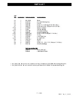
Page 17: ...037 SSF 927 DAC 161 NOTILLUSTRATED D20418 D20385 QUANTITY 1 1 1 1 1 1 1 1 1 1 1 1 1 1 1 4 1 DESCRIPTION Motor Eccentric Bearing Assy Fan Kit Screw 1 4 20 Torque 100 120 in lbs Screw Eccentric Torque100 120in lbs Sleeve Cylinder ConnectingRod CompressionRing ConnectingRodCap Screw 10 24 Torque61 70in lbs O ring Valve Plate Assy O ring Head Muffler Head Screw 1 4 20 x 1 1 4 Torque 7 10 ft lbs Shim R...

Page 18: ...ordered from any Sears Service Center and most Sears stores If the parts you need are not stocked locally your order will be electronically transmitted to a Sears Repair Parts Distribution Center for handling SERVICE SERVICE AND REPAIR PARTS CALL 1 800 665 4455 Keep this number handy should you require a service call or need to order repair parts If ordering parts make sure you have the name make ...

Page 19: ...ette d entretien apposée sur le moteur ou sur l étiquette du code à barres située à l arrière du réservoir 2 Le numéro de code de date indiqué sur l étiquette apposée à l arrière du réservoir d air 3 Le numéro de série indiqué sur l étiquette apposée à l arrière du réservoir d air 4 Le numéro d enregistrement du réservoir indiqué sur la plaque signalétique métallique située à l arrière du réservoi...

Page 20: ...ion particulière à ces sections CONSERVEZ CES DÉFINITIONS INSTRUCTIONS DANGER Indique un danger imminent qui s il n est pas évité causera de graves blessures ou la mort MISE EN GARDE sans le symbole d attention Indique la possibilité d un danger qui s il n est pas évité peut causer des dommages à la propriété AVERTISSEMENT Indique la possibilité d un danger qui s il n est pas évité pourrait causer...

Page 21: ...ACER LE COMPRESSEUR AU COMPLET NE JAMAIS PERFORER AVEC UNE PERCEUSE SOUDER OU FAIRE UNE MODIFICATION QUELCONQUE AU RÉSERVOIR OU À SES ACCESSOIRES LE RÉSERVOIR EST CONÇU POUR SUBIR DES PRESSIONS DE SERVICE PARTICULIÈRES NE JAMAIS EFFECTUER DES RÉGLAGES NI SUBSTITUER DES PIÈCES POUR MODIFIER LES PRESSIONS DE SERVICE ÉTABLIES À L USINE POUR LE CONTRÔLE ESSENTIEL DE LA PRESSION D AIR IL FAUT POSER UN ...

Page 22: ...NEJAMAISINHALERL AIRÉMISPARLECOMPRESSEUR QUECESOIT DIRECTEMENTOUAUMOYEND UNDISPOSITIFRESPIRATEURBRANCHÉAU COMPRESSEUR TRAVAILLERDANSUNENDROITOÙILYAUNEBONNEVENTILATION TRANSVERSALE BIENLIREETRESPECTERLESDIRECTIVESDESÉCURITÉ INDIQUÉESSURL ÉTIQUETTEOULAFICHESIGNALÉTIQUEDELAMATIÈREQUI ESTVAPORISÉE PORTERUNRESPIRATEURHOMOLOGUÉPARLENIOSH MSHAETCONÇUPOURL APPLICATIONENQUESTION DANGER RISQUE PRÉVENTION RI...

Page 23: ...UTESAPRÈSLEURFONCTIONNEMENT NEPASTENTERD ATTEINDRELESCOMPOSANTESDERRIÈRELESGARDESDE PROTECTIONETNEPASEFFECTUERDEL ENTRETIENAVANTD AVOIRLAISSÉ REFROIDIRL APPAREIL RISQUE PRÉVENTION UNCOMPRESSEURPORTATIFPEUTTOMBERD UNETABLE D UNÉTABLIOU D UNTOIT L IMPACTPEUTCAUSERDESDOMMAGESAUCOMPRESSEURET DESBLESSURESCORPORELLESOULAMORTDEL UTILISATEUR TOUJOURSS ASSURERDELASTABILITÉDUCOMPRESSEURAVANTDELE FAIREFONCTI...

Page 24: ...tilisé dans ce genre d applications Des filtres à air déshydrateurs supplémentaires qui éliminent les impuretés et l humidité contenues dans l air doivent être branchés au tuyau dans certains cas Si l on désire un réglage de pression très précis de l outil l ajout d un second détendeur est recommandé Ce niveau est appelé point de déclenchement du pressostat Cut in pressure Point de consigne d arrê...

Page 25: ...t évacuer l air à un point de pression préalablement fixé par le fabricant de la soupape légèrement supérieur au point d arrêt Régulateur de pression La pression de l air arrivant du réservoir est contrôlée par le bouton du régulateur Le bouton est du type insensible aux vibrations Tirer le bouton vers le haut pour modifier la pression et le presser vers le bas pour le bloquer Tourner le bouton da...

Page 26: ...isques d électrocution Cet appareil doit être mis à la masse correctement Le compresseur est équipé d un cordon d alimentation dont la fiche est pourvue d une broche de mise à la masse Cette fiche doit être branchée à une prise com patible ayant une mise à la masse conforme aux réglementslocaux Laprisedoitavoirlamêmeformeque la fiche Inspecter la fiche et la prise chaque fois qu on branche lecompr...

Page 27: ... levier AUTO O est à la position O et que le détendeur est fermé 2 Brancher le boyau et les accessoires Une pression d air excessive est un danger potentiel pouvant provoquer l éclatement d un outil Suivre scrupuleusement les étapes 3 et 5 suivantes chaque fois qu on utilise le compresseur L air comprimé peut contenir de l eau de conden sation Ne pas vaporiser avec de l air comprimé non filtré des...

Page 28: ...seur est accessible Attendre que le compresseur refroidisse avant de procéder aux travaux d entretien Filtre à air Maintenir toujours le filtre à air propre Ne pas faire fonctionner le compresseur sans filtre à air Un filtre sale ne permet pas au compresseur de fonctionner à sa capacité maximale Donc avant de faire fonctionner le compresseur s assurer que le filtre à air est propre Clapet de reten...

Page 29: ...tredeserviceSearspourremplacer le pressostat et le détendeur de pression Vérifier si la tige qui se trouve au bas du détendeur de pression est coincée Si elle ne se déplace pas facilement retournez le compresseur au Centre de service pour faire remplacer le pressostat Un clapet défecteux laisse fuir l air par le détendeur quand le moteur est à l arrêt et que le réservoir est souspression Démonterl...

Page 30: ...utomatiquementaussitôt que la pression du réservoir baisse au niveau du point déclenchement du pressostat 1 Vérifier fusible ou disjoncteur Remplacer ou réarmer Ne pas utiliser un fusible ou un disjoncteur de calibre supérieur à la capacité du circuit 2 Vérifier le type de fusible N utiliser que des fusibles à action différée 3 Vérifier la tension d alimentation Vérifier le calibre de la rallonge ...

Page 31: ...13 FR D20418 Rev 0 2 22 00 Dépannage Pièces ...

Page 32: ...14 FR D20418 Rev 0 2 22 00 SCHÉMA APPAREIL ...

Page 33: ...23 1 H 2101 Adaptateur 24 1 AC 0375 Pressostat 26 2 SSP 7811 Écrou Manchon 27 1 AC 0028 Tube de dégagement de pression 31 1 SSP 7821 1 Écrou de compression serrage 120 140 po lb 32 1 SSG 3105 Jointtorique 33 1 SSP 7813 Écrou Manchon serrage à la main un tour 34 1 AC 0097 Tuyauderefoulement 37 1 SUDL 413 2 Cordond alimentation 38 2 ACG 18 Rondelle creuse étrier 39 2 91895680 Vis 1 4 20 x 0 75 serra...

Page 34: ...16 FR D20418 Rev 0 2 22 00 SCHÉMA BLOC COMPRESSEUR ...

Page 35: ... 61 70 po lbs 63 1 SSG 8156 Jointtorique 64 1 AC 0032 Plateau de soupapes 65 1 ACG 45 Joint torique culasse 66 1 CAC 1371 Silencieux 67 1 AC 0037 Culasse 68 4 SSF 927 Vis 1 4 20 x 1 1 4 serrage 7 10 pi lbs 69 1 DAC 161 Joint d espacement bords arrondis Non illustré D20418 OwnersManual anglais D20418 Manuel de l usager français D20385 Étiquette de spécifictions Les réf 58 59 60 61 62 65 peuvent êtr...

Page 36: ... des magasins Sears Si le magasin Sears auquel s adresse le client n a pas en stock les pièces désirées la commande sera transmise par ordinateur à un centre de distribution de pièces de rechange Sears pour en accélérer le traitement et l expédition POUR COMMANDER DES PIÈCES DE RECHANGE ENTRETIEN ET PIÈCES DE RECHANGE COMPOSEZ 1 800 665 4455 Conservez ce numéro à portée de la main au cas où vousau...

Reviews: