background image

19

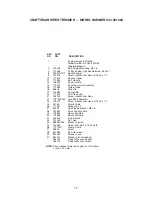
CRAFTSMAN WEED TRIMMER - - MODEL NUMBER 944.361063

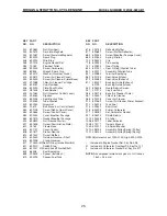
 KEY     PART            
 NO.     NO.                  DESCRIPTION

    1      174031X558    Chassis Assembly
    2      182133             Line, Trimmer  .155 diameter x 18.75 long
    3      173715             Screw, Self-Tapping   5/16-18 x 1
    4      185476             V-Belt
    5      172145X004    Bracket, Idler
    6      166042             Pulley, Idler, V-Groove
    7      173716             Bolt, Hex Head  3/8-16 x 1.25
    8      751592             Locknut, Hex  3/8-16
    9      166043             Pulley, Idler, Flat
  10      160829             Bolt, Shoulder
  11      155552             Locknut  5/16-18
  12      173717             Spacer
  13      174719             Bolt, Shoulder
  14      145212             Locknut, Flange
  15      173811             Spring, Return
  16      180268             Defl ector, Bottom
  17      57808               Screw  1/4-20 x 1/2
  18      178848             Screw  #10-24 x 3/4
  20      170553             Cover, Chassis, Top
  21      149746             Screw  #10-24 x 1-3/4
  22      STD541137     Nut, Hex  3/8-24 UNF
  23      STD551137     Washer, Lock  3/8
  24      STD551037     Washer, Flat  3/8
  25      180340             Pulley, Driven
  26      172551             Spacer, Pulley
  27      174549             Bearing
  28      172520             Jackshaft
  29      169766X479    Cover, Chassis, Bottom
  30      174543             Spindle Housing Assembly
                                    (* Includes Upper Bearing, Key Number 27)
  31      174581             Ring, Retaining, External, 17mm
  32      176973             Spring, Locking Plate
  33      172519             Locking Plate
  34      180338             Carrier Plate Assembly
  35      182217             Mow Ball Assembly
                                    (Includes Key Numbers 27, 37 and 38)
  36      172516             Cover, Bearing
  37      174580             Ring, Retaining, Internal, 40mm
  38      172523             Mow Ball
  39      180334             Bolt, Mow Ball
  40      180333             Spindle Assembly, Complete
                                    (Includes Key Numbers 22-28 and 30-39)
  41      174029             Spacer
  43      174042             Decal, Instruction
  44      174035             Decal, Chassis Cover
  45      174596X479    Belt Keeper, Bottom
  46      17060408         Screw, Self-Tapping
  47      174510             Decal, Instruction
  51      179875             Defl ector, Rear
  52      178848             Screw
  53      187336             Belt Keeper

NOTE:

  All component dimensions given in U.S. inches

            1 inch = 25.4 mm

Summary of Contents for 944.361063

Page 1: ... No 944 361063 CAUTION Read and follow all Safety Rules and Instructions before operating this equipment Owner s Manual WHEELED WEEDTRIMMER 6 0 Horsepower 22 Inch Cut Sears Canada Inc Toronto Ontario M5B 2B8 ...

Page 2: ...anual Warranty service is available by returning the Craftsman Weedtrimmer to the nearest Sears Service Centre Department in Canada This warranty applies only while this prod uct is used in Canada This warranty is in addition to any statutory warranty and does not exclude or limit legal rights you may have but shall run concurrently with applicable provincial legislation Fur thermore some province...

Page 3: ...llow it to cool before cleaning repairing or inspecting the unit Be sure the trimmer head and all moving parts have stopped Operate only in daylight or good artificial light Do not operate the machine while under the influence of alcohol or drugs Never operate machine in wet grass Al ways be sure of your footing keep a firm hold on the handle and walk never run If the equipment should start to vib...

Page 4: ...n to operate the machine Use extra care when approaching blind corners shrubs trees or other objects that may obscure vision IV SERVICE Use extra care in handling gasoline and other fuels They are flammable and vapors are explosive Use only an approved container Never remove gas cap or add fuel with the engine running Allow engine to cool before refueling Do not smoke Never refuel the machine indo...

Page 5: ...n standing behind the handle TO REMOVE TRIMMER FROM CARTON 1 Remove loose parts included with trim mer 2 Cut down two end corners of carton and lay end panel down flat 3 Remove all packing materials 4 Roll trimmer out of carton and check carton thoroughly for additional loose parts HOW TO SET UP YOUR TRIMMER TO UNFOLD HANDLE IMPORTANT Unfold handle carefully so as not to pinch or damage control ca...

Page 6: ...k Chassis cover Trimmer head control bar Throttle control Throttle control used for starting and stopping the engine and allows you to select either fast or slow engine speed Starter handle used for starting the engine Trimmer head control bar must be held down to the handle to engage trimmer head Release to stop the trimmer head Primer pumps additional fuel from the carburetor to the cylinder for...

Page 7: ...ion 2 Release tab and be sure head is locked into one of the six 6 height positions TRIMMER HEAD DRIVE CONTROL Your trimmer is equipped with a trimmer head drive control bar which will require the operator to be positioned behind the trimmer handle to operate the trimmer Trimmer head rotation is controlled by holding the trimmer head control bar down to the handle Trimmer head rotation will stop w...

Page 8: ...ess CAUTION Alcohol blended fuels called gasohol or using ethanol or methanol can attract moisture which leads to separation and formation of acids during storage Acidic gas can damage the fuel system of an engine while in storage To avoid engine problems the fuel system should be emptied before storage of 30 days or longer Drain the gas tank start the engine and let it run until the fuel lines an...

Page 9: ... level 2 Check for loose fasteners 3 Clean under engine cover LUBRICATION To prolong the useful life of your trimmer change engine oil as recommended in this section of this Owner s Manual IMPORTANT Do not oil or grease plastic wheel bearings Viscous lubricants will attract dust and dirt that will shorten the life of the self lubricating bearings If you feel they must be lubricated use only a dry ...

Page 10: ...off during trimming and become a dangerous missile that can cause serious injury TO CUT LINE TO PROPER LENGTH NOTE Trimmer line pre cut to proper length is available for this unit see the Repair Parts section of this manual If trimmer line is purchased in bulk it must be cut to 18 3 4 inches before using Use the built in length guage as follows 1 From front of trimmer place the end of spooled trim...

Page 11: ...idge Cover 4 Wipe off any spilled oil from trimmer or side of engine 5 Fill engine with oil See ADD OIL in the Operation section of this manual 6 Replace engine oil cap 7 Reconnect spark plug wire to plug AIR FILTER Your engine will not run properly and may be damaged by using a dirty air filter Replace the air filter cartridge every 100 hours of operation or every season which ever occurs first S...

Page 12: ...ST TRIMMING HEIGHT in the Operation section of this manual TO ADJUST HANDLE The upper handle may be adjusted to dif ferent height positions 1 Loosen handle knob only enough to allow the upper handle to pivot to the desired position 2 Tighten handle knob securely NOTE The handle knob and bolt may be reversed for left handed operation Debris shield screws Engine pulley 3 Remove the two 2 screws on s...

Page 13: ...pulleys and bottom belt keeper to idler bracket Tighten pulley bolts securely NOTE Be sure belt is inside top belt keeper on idler assembly ENGINE ENGINE SPEED Your engine speed has been factory set Do not attempt to increase engine speed or it may result in personal injury If you believe that the engine is running too fast or too slow take your unit to a Sears or other qualified service center fo...

Page 14: ...nd carburetor are empty Never use engine or carburetor cleaner products in the fuel tank or permanent damage may occur Use fresh fuel next season NOTE Fuel stabilizer is an acceptable alternative in minimizing the formation of fuel gum deposits during storage Add stabilizer to gasoline in fuel tank or storage container Always follow the mix ratio found on stabilizer container Run engine at least 1...

Page 15: ...lts 2 Check all hardware including engine bolts 3 Damaged trimmer head 3 Check repair trimmer head Starter rope 1 Bent engine crankshaft 1 Contact a Sears or other hard to pull qualified service center Loss of head 1 Belt not driving 1 Put belt on pulleys or drive replace belt if broken Hard to push 1 Handle height position not 1 Adjust handle height right for you to suit Poor trimming 1 Trimmer l...

Page 16: ...16 CRAFTSMAN WEED TRIMMER MODEL NUMBER 944 361063 REPAIR PARTS 32 11 18 20 33 12 15 15 9 8 9 26 27 23 24 22 2 3 40 38 39 23 24 10 16 21 26 27 19 28 35 34 37 36 1 29 30 ...

Page 17: ...55 Screw Hex Washer Head 22 178702X004 Axle Shaft Assembly 23 150078 Screw Hex Washer Head 5 16 18 x 75 24 52160 Washer Axle 26 177637 Wheel 16 x 2 27 83923 Hex Flange Locknut 3 8 16 28 181699 Drive Control Cable 29 178844 Decal Warning 30 178365 Decal Warning 32 164265 Grip Handle 33 132004 Nut Hex 34 86899X004 Bracket Upstop 35 750634 Screw Thd Roll 10 24 x 5 8 36 111190X Clamp Cable 37 83816 Sc...

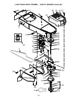
Page 18: ...18 CRAFTSMAN WEED TRIMMER MODEL NUMBER 944 361063 12 43 14 1 52 51 17 4 13 53 16 18 34 33 39 38 27 37 27 30 36 31 35 32 3 3 22 23 24 25 26 27 28 9 10 7 6 41 5 8 11 15 29 40 45 21 47 46 20 44 2 ...

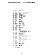
Page 19: ... Lock 3 8 24 STD551037 Washer Flat 3 8 25 180340 Pulley Driven 26 172551 Spacer Pulley 27 174549 Bearing 28 172520 Jackshaft 29 169766X479 Cover Chassis Bottom 30 174543 Spindle Housing Assembly Includes Upper Bearing Key Number 27 31 174581 Ring Retaining External 17mm 32 176973 Spring Locking Plate 33 172519 Locking Plate 34 180338 Carrier Plate Assembly 35 182217 Mow Ball Assembly Includes Key ...

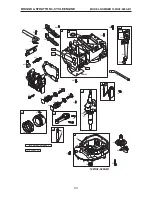
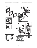
Page 20: ... CYCLE ENGINE 122H02 0220 B1 50 51 54 584 684 585 383 337 635 5 7 306 307 13 34 33 35 36 40 40 45 45 24 523 847 842 871 870 869 1 2 3 287 525 524 11 8 9 10 16 146 741 32 32A 29 28 27 27 26 25 12 15 20 4 1058 OWNER S MANUAL 46 43 22 1019 LABEL KIT 718 ...

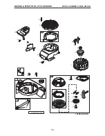
Page 21: ...22H02 0220 B1 300 222 966 976 125 97 134 133 121 CARBURETOR OVERHAUL KIT 977 CARBURETOR GASKET SET 163 529 970 159 188 425 968 967 445 443 276 137 617 95 130 127 163 633 613 81 365 127 104 163 276 617 633 137 137 633 163 617 975 117 276 668 621 276 677 676 104 118 276 ...

Page 22: ...MBER 122H02 0220 B1 BRIGGS STRATTON 4 CYCLE ENGINE 597 456 689 459 60 1210 1211 58 592 65 55 957 670 190 305 23 455 332 363 304 37 78 564 604 949 563 703 1036 EMISSION LABEL 122H02 0220 B1 972 608 1059 187 601 997 ...

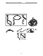
Page 23: ...23 MODEL NUMBER 122H02 0220 B1 BRIGGS STRATTON 4 CYCLE ENGINE 842 9 12 524 51 3 20 585 7 163 617 358 ENGINE GASKET SET 668 122H02 0220 B1 851 334 48 333 227 356 616 404 615 202 209 505 562 ...

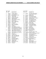
Page 24: ... 40 692194 Retainer Valve 43 691997 Slinger Governor Oil 45 690548 Tappet Valve 46 691449 Camshaft KEY PART NO NO DESCRIPTION 48 498826 Short Block Replacement Engine 125H02 0005 D1 50 497465 Manifold Intake 51 272199 Gasket Intake 54 691650 Screw Intake Manifold 55 697670 Housing Rewind Starter 58 692259 Rope Starter Cut to Length 60 281434 Grip Starter Rope 65 690837 Screw Rewind Starter 78 6911...

Page 25: ... 66538 Boot Sparkplug 668 493823 Spacer Includes 2 670 692294 Spacer Fuel Tank KEY PART NO NO DESCRIPTION 676 393760 Deflector Muffler 677 690661 Screw Muffler Deflector 684 690345 Screw Breather Passage Cover 689 691855 Spring Friction 703 696309 Clip 718 690959 Pin Locating 741 691830 Gear Timing 842 691031 Seal O Ring Dipstick Tube 847 692017 Assembly Dipstick Tube 851 493880 Terminal Sparkplug...

Page 26: ...26 SERVICE NOTES ...

Page 27: ...27 ...

Page 28: ...186744 Rev 1 06 18 03 BY Printed in U S A ...

Reviews: