background image

17

CRAFTSMAN R

O

T

A

R

Y

 LA

WN MO

WER - - MODEL NUMBER 944.361543

KEY


P

A

R

T


NO

.


NO

.              


DESCRIPTION

 38 

164362 


Shoulder 

Bolt

 39 

83923 


Flanged 

Loc

kn

ut

 40 

77400 


Hubcap

 41 

88652 


Hinge 

Scre

w

 42 

165766 


Spr

ing 

(LH)

 43 

165767 


Spr

ing 

(RH)

 44 

185819 


Door 

Bolt

 45 

150406 


He

x Head 

Thread Rolling Scre

w 3/8-16 x 1

 46 

107339X 


Danger 

Decal

 47 

63124 


Nut

 48 

180410X004 


Axle Ar

m Assemb

ly - RR

 49 

180182 


Wheel

 50 

57143 


W

a

v

e

 W

asher

 51 

73990500 


Nut

 52 

173319 


Housing Assemb

ly (Incl.

 Ref

. #17, 18 & 46)

 53 

851084 


He

x Head Scre

w 3/8-24 x 1-3/8 Grd.

 8

 54 

850263 


Helical 

Loc

kw

asher

 55 

851074 


Hardened 

W

asher

 56 

175064 


21" 

Blade

 57 

851514 


Blade 

Adapter

 58 

161551 


Adjustment 

Bolt

 67 

186018 


Gr

ass 

Bag

 68 

180332 


Catcher 

F

rame

 70 

   - - - 


Engine

, Br

iggs & Str

atton, Model Number


12H802-1901-B1 (See Breakdo

w

n)

 71 

751152 


Nut, He

x, Flangeloc

k  1/4-20


- - 

162300 


W

a

rning Decal (Not Sho

wn)


- - 

186682 


Owner’

s Man

ual, English


- - 

186683 


Owner’

s Man

ual, F

rench

NO

TE:

 All component dimensions giv

en in U

.S

. inches

.

           1 inch = 25.4 mm


1  

131696 


Control Bar

 2 

166860X479 


Upper 

Handle

 3 

161105X479 


Lo

w

er 

Handle


186079 


Rope Guide / Anti-F

old Br

ac

k

e

t

 5 

132004 


Loc

kn

ut 

1/4-20

 6 

131959 


Handle 

Bolt

 7 

66426 


Wire 

Tie


74780512 


He

x Bolt 5/16-18 x 3/4

 9 

168360X004 


Selector 

Spr

ing

 11 

176556 


Engine Zone Control Cab

le

 12 

750634 


He

W

a

sher Head Scre

w #10-24 x 1/2

 13 

86899X004 


Up-Stop 

Br

ac

k

e

t

 14 

136376 


Handle 

Knob

 15 

51793 


Hair

pin 

Cotter

 17 

165946X479 


Suppor

Br

ac

k

e

t

 18 

17600406 


Scre

w

 19 

167132X004 


Axle Ar

m Assemb

ly - LF

 20 

167133X004 


Axle Ar

m Assemb

ly - RF

 21 

165858 


Rear 

Skir

t

 22 

180080X004 


Selector 

Spr

ing

 23 

186612 


Rear Door Assemb

ly Kit (Includes Spr

ings)

 24 

73930500 


Loc

kn

ut 

5/16-18

 25 

186212X479 


Handle Br

ac

k

e

t Assemb

ly (Left)

 26 

186213X479 


Handle Br

ac

k

e

t Assemb

ly (Right)

 27 

851856 


Scre

w 1/4-20 x 3/8

 29 

160835X007 


Wheel Adjusting Br

ac

k

e

t - F

ront

 30 

183901 


Spacer

 33 

87877 


Selector 

Knob

 34 

180409X004 


Axle Ar

m Assemb

ly - LR

 35 

166785 


Loc

kn

ut 

5/16-18

 36 

160828 


Shoulder Bolt 5/16-18

 37 

151162 


Wheel 

Assemb

ly

KEY


P

A

R

T


NO

.


NO

.              


DESCRIPTION

Summary of Contents for 944.361543

Page 1: ...o 944 361543 CAUTION Read and follow all Safety Rules and Instructions before operating this equipment Owner s Manual ROTARY LAWN MOWER 6 0 Horsepower 21 Rear Discharge Sears Canada Inc Toronto Ontario M5B 2B8 ...

Page 2: ...ing up transporting adjusting or making repairs CAUTION Muffler and other engine parts become extremely hot during operation and remain hot after engine has stopped To avoid severe burns on contact stay away from these areas LIMITED TWO YEAR WARRANTY ON CRAFTSMAN POWER MOWER For Two years from date of purchase Sears Canada Inc will repair or replace at Sears option free of charge parts which are d...

Page 3: ...rass Reduced footing could cause slipping III CHILDREN Tragic accidents can occur if the operator is notalerttothepresenceofchildren Children are often attracted to the machine and the mowing activity Never assume that children will remain where you last saw them Keep children out of the trimming area and under the watchful care of another responsible adult Be alert and turn machine off if childre...

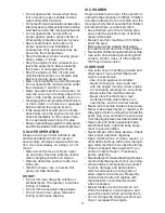
Page 4: ...D HANDLE IMPORTANT Unfold handle carefully so as not to pinch or damage control cables 1 Raise lower handle section to operat ing position and squeeze the bottom ends of lower handle towards each other until the pin in handle can be inserted into one of the three height adjustment holes 2 Remove protective padding raise up per handle section into place on lower handle and tighten both handle knobs...

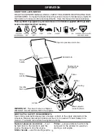
Page 5: ...rs rotary walk behind power lawn mowers conform to the safety standards of the American National Standards Institute and the U S Consumer Product Safety Com mission The blade turns when the engine is running Operator presence control bar must be held down to the handle to start the engine Release to stop the engine Starter handle used for starting engine These symbols may appear on your lawn mower...

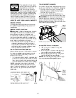
Page 6: ...ing height to suit your requirements Medium position is best for most lawns To change cutting height squeeze ad juster lever toward wheel Move wheel up or down to suit your requirements Be sure all wheels are in the same setting NOTE Adjuster is properly positioned when plate tab inserts into hole in lever Also 9 position adjusters if so equipped allow lever to be positioned between the plate tabs...

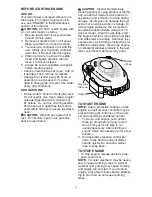
Page 7: ...e CAUTION Alcohol blended fuels called gasohol or using ethanol or metha nol can attract moisture which leads to separation and formation of acids during storage Acidic gas can damage the fuel system of an engine while in storage To avoid engine problems the fuel system should be emptied before storage of 30 days or longer Drain the gas tank start the engine and let it run until the fuel lines and...

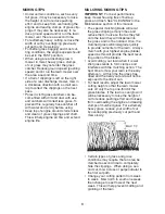
Page 8: ...g free of built up grass and trash See CLEANING in the Maintenance section of this manual The special mulching blade will recut the grass clippings many times and reduce them in size so that as they fall onto the lawn they will disperse into the grass and not be noticed Also the mulched grass will biodegrade quickly to provide nutrients for the lawn Always mulch with your highest engine blade spee...

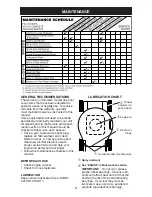
Page 9: ...ent and check blade for wear A new spark plug and clean new air filter element assure proper air fuel mixture and help your engine run better and last longer Follow the maintenance schedule in this manual BEFORE EACH USE Check engine oil level Check for loose fasteners LUBRICATION Keep unit well lubricated See LUBRI CATION CHART Spray lubricant See ENGINE in Maintenance section IMPORTANT Do not oi...

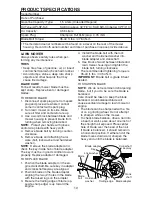
Page 10: ...heck the key inside hub of blade adapter The key must be in good condition to work properly Replace adapter if damaged TO REPLACE BLADE 1 Position the blade adapter on the en gine crankshaft Be sure key in adapter and crankshaft keyway are aligned 2 Position blade on the blade adapter aligning the two 2 holes in the blade with the raised lugs on the adapter 3 Be sure the trailing edge of blade op ...

Page 11: ...the engine and after each five 5 hours of continuous use Tighten oil plug securely each time you check the oil level TO CHANGE ENGINE OIL NOTE Before tipping lawn mower to drain oil drain fuel tank by running engine until fuel tank is empty 1 Disconnect spark plug wire from spark plug and place wire where it cannot come in contact with spark plug 2 Remove engine oil cap lay aside on a clean surfac...

Page 12: ...r after every 100 hours of operation whichever occurs first Spark plug type and gap setting are shown in PRODUCT SPECIFICATIONS in Maintenance section of this manual CLEANING IMPORTANT For best performance keep mower housing free of built up grass and trash Clean the underside of your mower after each use WARNING To avoid serious injury before performing any service or adjust ments 1 Release contr...

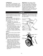
Page 13: ...tenance section of this manual 3 Be sure that all nuts bolts screws and pins are securely fastened Inspect moving parts for damage breakage and wear Replace if necessary 4 Touch up all rusted or chipped paint surfaces sand lightly before painting HANDLE You can fold your lawn mower handle for storage NOTE The upper handle has an anti fold bracket located on the right side of the handle This bracke...

Page 14: ...mage the fuel system of an engine while in storage 1 Drain the fuel tank 2 Start the engine and let it run until the fuel lines and carburetor are empty Never use engine or carburetor cleaner products in the fuel tank or permanent damage may occur Use fresh fuel next season NOTE Fuel stabilizer is an acceptable alternative in minimizing the formation of fuel gum deposits during storage Add stabili...

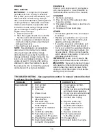
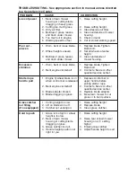
Page 15: ...ter rope 1 Engine flywheel brake is on 1 Depress control bar to hard to pull when control bar is released upper handle before pulling starter rope 2 Bent engine crankshaft 2 Contact a Sears or other qualified service center 3 Blade adapter broken 3 Replace blade adapter 4 Blade dragging in grass 4 Move lawn mower to cut grass or to hard surface Grass catcher 1 Cutting height too low 1 Raise cuttin...

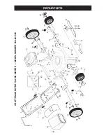
Page 16: ...16 REPAIR PARTS CRAFTSMAN ROTARY LAWN MOWER MODEL NUMBER 944 361543 ...

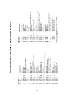
Page 17: ...rench NOTE All component dimensions given in U S inches 1 inch 25 4 mm 1 131696 Control Bar 2 166860X479 Upper Handle 3 161105X479 Lower Handle 4 186079 Rope Guide Anti Fold Bracket 5 132004 Locknut 1 4 20 6 131959 Handle Bolt 7 66426 Wire Tie 8 74780512 Hex Bolt 5 16 18 x 3 4 9 168360X004 Selector Spring 11 176556 Engine Zone Control Cable 12 750634 Hex Washer Head Screw 10 24 x 1 2 13 86899X004 ...

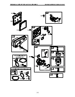
Page 18: ...LE ENGINE 307 13 337 635 383 3 306 11 9 10 54 50 51 7 5 584 585 684 287 525 524 842 1019 LABEL KIT 1058 OWNER S MANUAL 1 2 8 847 523 869 870 871 27 27 32 26 28 25 29 40 40 35 36 33 45 34 45 24 741 16 146 20 12 22 46 43 15 4 1095 VALVE GASKET SET 7 9 32A ...

Page 19: ...CLE ENGINE 104 137 276 95 127 633 617 276 130 365 125 97 134 975 133 117 163 968 445 425 443 163 529 159 970 966 976 188 222 104 137 276 127 633 121 CARBURETOR OVERHAUL KIT 617 137 276 633 617 977 CARBURETOR GASKET SET 163 163 134 81 613 300 668 276 118 ...

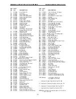
Page 20: ...d Cylinder 7 692249 Gasket Cylinder Head 8 695250 Breather Assembly 9 696125 Gasket Breather 10 691125 Screw Breather Assembly 11 499675 Tube Breather 12 692232 Gasket Crankcase 13 690912 Screw Cylinder Head 15 691680 Plug Oil Drain KEY PART NO NO DESCRIPTION 16 691451 Crankshaft 20 399781 Seal Oil PTO Side 22 691092 Screw Engine Sump 23 692315 Flywheel 24 222698 Key Flywheel 25 499429 Piston Asse...

Page 21: ...or 383 89838 Wrench Spark Plug 404 690272 Washer Governor Crank 425 690670 Screw Air Cleaner Cover 443 692523 Screw Air Cleaner Primer Base KEY PART NO NO DESCRIPTION 445 491588 Filter Air Cleaner Cartridge 456 692299 Plate Pawl Friction 459 281505 Pawl Ratchet 505 691251 Nut Governor Control Lever 523 495264 Dipstick 524 692296 Seal Dipstick Tube 525 495265 Tube Dipstick 529 691923 Grommet 562 69...

Page 22: ...22 SERVICE NOTES ...

Page 23: ...23 SERVICE NOTES ...

Page 24: ...186682 03 27 03 BY Printed in U S A ...

Reviews: