background image

6

ASSEMBLY / PRE-OPERATION

Read these instructions and this manual 

in its entirety before you attempt to as-

semble or operate your new lawn mower.  

IMPORTANT:

  This lawn mower is 

shipped WITHOUT OIL OR GASOLINE in 

the engine.

Your new lawn mower has been as sem-

 bled at the factory with the exception of 

those parts left unassembled for shipping 

purposes.  All parts such as nuts, wash-

ers, bolts, etc., nec es sary to complete the 

as sem bly have been placed in the parts 

bag.  To ensure safe and proper operation 

of your lawn mower, all parts and hard-

 ware you assemble must be tightened 

securely.  Use the correct tools as neces-

sary to ensure proper tightness.  

TO REMOVE MOWER FROM 

CAR TON

1.  Remove loose parts included with 

mower.

2.  Cut down two end corners of  carton 

and lay end panel down flat.

3.  Remove all packing materials except 

padding between upper and lower 

handle and padding holding operator 

presence control bar to upper handle.

4.  Roll mower out of carton and check 

carton thor ough ly for additional loose 

parts. 

MOWING 

POSITION

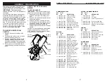
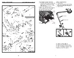
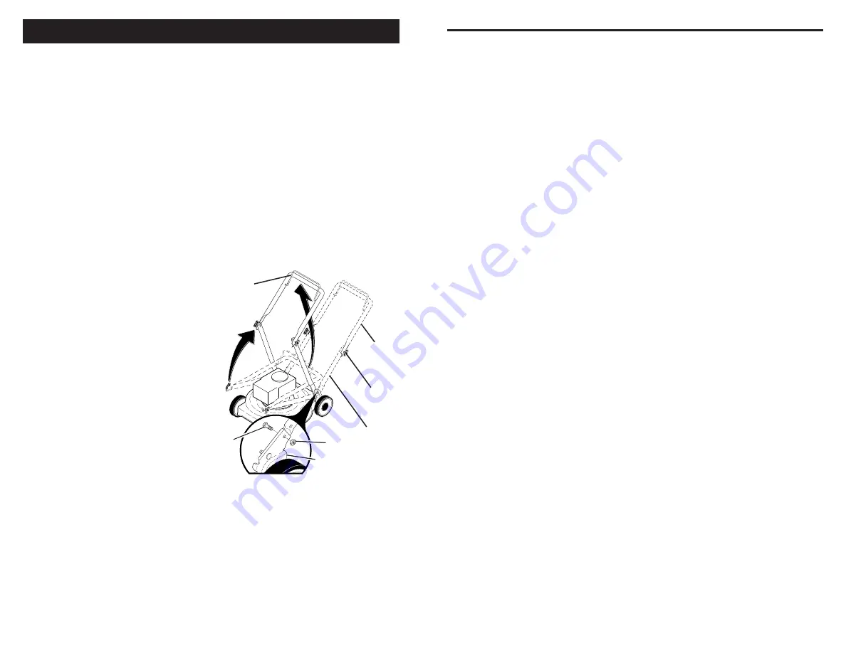
Lower handle

LIFT 

UP

Operator 

presence 

control bar

Bolt

Nut

Bracket

Upper 

handle

LIFT 

UP

Handle 

knob

HOW TO SET UP YOUR LAWN 

MOW ER 

TO UNFOLD HANDLE

IMPORTANT

:  Unfold handle carefully so 

as not to pinch or damage con trol cables. 

1.  Raise handles until lower handle sec-

tion locks into place in mowing posi-

tion.

2.  Insert bolt through handle and bracket 

and secure with nut.

3.  Remove protective padding, raise up-

per handle sec tion into place on lower 

handle and tighten both handle knobs.

4.  Remove handle padding holding 

operator pres ence control bar to upper 

handle.

Your lawn mower handle can be adjusted 

for your mowing comfort. Refer to "AD-

 JUST HANDLE" in the Service and Adjust-

ments section of this manual.

27

MODEL NUMBER GCV160-LAOS3B

HONDA 4-CYCLE ENGINE

 CAMSHAFT PULLEY


KEY     PART

NO.      NO. 

DESCRIPTION

 1  14320-ZL8-010  Pulley, Camshaft

  2  14324-ZL8-000  Shaft, Cam Pulley

 3  14400-Z0J-014  Belt, Timing


(84HU7 

G-200)

  6  14461-ZL8-000  Shaft, Rocker Arm

 11  90112-333-000  Screw, Tappet Adjusting

 12  90206-001-000  Nut, Tappet Adjusting

 13  91301-ZM0-V31  O-Ring (6.8 x 1.9) (ARAI)

15  14431-Z0J-000  Rocker Arm, Intake Valve 

 16 14441-Z0J-000  Rocker Arm,


Exhaust 

Valve

OIL PAN

KEY     PART

NO.      NO. 

DESCRIPTION

  1  11300-ZM0-811  Pan Assembly, Oil

 2  15650-ZM0-801  Gauge Assembly,


Oil 

Level

  4  15625-ZE6-000  Gasket, Oil Filler Cap

  5  15631-ZM0-000  Extension, Oil Filler

  6  15639-ZM0-000  Lock Washer, Extension

  8  16508-ZM0-010  Shaft, Governor Holder

 9  16510-ZM0-010  Governor Assembly

 10 16511-ZL8-000  Weight, Governor

 11  16512-ZM0-000  Holder, Governor Weight

 12  16513-ZE1-000  Pin, Governor Weight

 13 16531-ZE1-000  Slider, Governor

 14  16541-ZM0-000  Shaft, Governor Arm

 15  90014-952-000  Bolt, Flange (#6 x 14)


(CT200)

 16  90121-952-000  Bolt, Flange (#6 x 25)


(CT200)

 17  90451-ZE1-000  Washer, Thrust (6 mm)

 18  90602-ZE1-000  Clip, Governor Holder

 19  91202-ZL8-003  Oil Seal (28 x 41.25 x 6)

 20  91356-MA6-005  O-Ring (14.8 x 2.4) (NOK)

 21  94101-068000  Washer, Plain (6 mm)

 22  94251-08000 

Pin, Lock (8 mm)

 23  94301-08200 

Pin, Dowel (#8 x 20)

PISTON / CONNECTING ROD

KEY     PART

NO.      NO. 

DESCRIPTION

 1  13101-Z2A-010  Piston

 2  13111-ZE0-000  Pin, Piston

  3  13200-Z0J-000  Connecting Rod Assem-

bly

  4  90001-ZE1-000  Bolt, Connecting Rod

  5  90551-ZE0-000  Clip, Piston Pin (13 mm)

  6  13010-Z0L-014  Ring Set, Piston, Standard


(Teikoku)

 LABELS

KEY     PART

NO.      NO. 

DESCRIPTION

  9  87528-Z0L-V20  Mark, Choke Indication 

 20 87114-ZH7-821  Label, Warning

 30  87101-Z8B-000  Mark, Emblem (GCV160)

 31  87169-Z8E-000  Mark, Recoil Cover

 32 87524-Z8B-000  Mark, Caution,


Fuel 

Petcock


 CHOKE BASE

KEY     PART

NO.      NO. 

DESCRIPTION

 2  16592-Z2D-800  Spring, Return

  5  16614-Z2D-800  Spring, Choke Lever

 8  16632-Z0L-801  Rod, Stop

  9  90022-888-010  Bolt, Flange (#6 x 20)


(CT200)

 14  16610-Z2D-801  Lever Assembly, Choke

    16610-Z2D-802  Lever Assembly, Choke

Summary of Contents for 944.364152

Page 1: ...Y Printed in U S A Model No 944 364152 CAUTION Read and follow all Safety Rules and Instructions before operating this equipment Owner s Manual ROTARY LAWN MOWER 160cc Honda Engine 21 Multi Cut Sears Canada Inc Toronto Ontario M5B 2B8 ...

Page 2: ...e sponsible adult other than the operator Be alert and turn machine off if children enter the area Beforeandwhilewalkingbackwards look behind and down for small children Never allow children to operate the machine II GENERAL OPERATION Read understand and follow all instructions on the machine and in the manual s before starting Be thoroughly familiar with the controls and the proper use of the mac...

Page 3: ... the engine running Allow engine to cool before refueling Never refuel the machine indoors Never store the machine or fuel contain er where there is an open flame spark or pilot light such as a water heater or on other appliances Never fill containers inside a vehicle on a truck or trailer bed with a plastic liner Always place containers on the ground away from your vehicle before filling Remove g...

Page 4: ... 888 888 3139 Email powerequipmentemissions ahm honda com or Honda Canada Inc Power Equipment Customer Relations Visit www honda ca for contact information Telephone 888 946 6329 Only Honda approved replacement parts may be used in the performance of any warranty repairs and must be provided without charge to the owner The use of replacement parts not equivalent to the original parts may impair th...

Page 5: ...is on the reverse side of this warranty statement Normal maintenance items such as spark plugs and filters that are on the warranted parts list are warranted up to their required replacement interval only Honda will also replace other engine components damaged by a failure of any warranted part dur ing the warranty period American Honda Motor Co Inc Power Equipment Customer Relations 4900 Marconi ...

Page 6: ...0 LAOS3B HONDA 4 CYCLE ENGINE CAMSHAFT PULLEY KEY PART NO NO DESCRIPTION 1 14320 ZL8 010 Pulley Camshaft 2 14324 ZL8 000 Shaft Cam Pulley 3 14400 Z0J 014 Belt Timing 84HU7 G 200 6 14461 ZL8 000 Shaft Rocker Arm 11 90112 333 000 Screw Tappet Adjusting 12 90206 001 000 Nut Tappet Adjusting 13 91301 ZM0 V31 O Ring 6 8 x 1 9 ARAI 15 14431 Z0J 000 Rocker Arm Intake Valve 16 14441 Z0J 000 Rocker Arm Exh...

Page 7: ... for a few minutes If bag gets wet let it dry before using TO INSTALL ATTACHMENTS Your lawn mower was shipped ready to be used as a mulcher To convert to bag ging see TO CONVERT MOWER in the Operation section of this manual Frame handle Frame opening Vinyl bindings INSTALL STARTER ROPE 1 Loosen T knob 2 Hold control bar against upper handle 3 Slowly pull engine starter rope out until rope will sli...

Page 8: ...y Fan T93 Husqvarna Grey 19610 Z0L 861ZE Cover Assembly Fan T98 M T D Red 22 19619 ZL8 300 Collar Fan Cover 24 90013 883 000 Bolt Flanged 6 x 12 CT200 25 90015 883 000 Bolt Flanged 6 x 28 CT200 27 90043 ZL8 000 Bolt Stud H 42 5mm 28 90043 ZL8 000 Bolt Stud H 42 5mm 33 93913 25220 Screw Tapping PO 5 x 12 35 91424 Z8B 821 Tube Fuel Tank 36 91427 Z8B 821 Tube Fuel 7 3 x 160 40 95002 40800 08 Clip Tub...

Page 9: ...lso 9 position adjusters if so equipped allow lever to be positioned between the plate tabs Pivot pins Grass catcher handle Catcher frame hook Rear door SIDE DISCHARGING Rear door must be closed Open mulcher door and install dis charge deflector under door as shown Mower is now ready for discharging operation To convert to mulching or bagging operation discharge deflector must be removed and mulch...

Page 10: ... the oil after every 25 hours of operation or each season You may need to change the oil more often under dusty dirty conditions See TO TO STOP ENGINE To stop engine release operator pres ence control bar Wait until blade and all moving parts have stopped and turn fuel valve to OFF position if you do not intend to restart the engine soon TO START ENGINE NOTE Due to protective coatings on the engin...

Page 11: ...ss conditions may require that an area be mulched a second time to completely hide the clippings When doing a sec ond cut mow across perpendicular to the first cut path Change your cutting pattern from week to week Mow north to south one week then change to east to west the next week This will help prevent matting and graining of the lawn MAX 1 3 MOWING TIPS CAUTION Do not use de thatcher blade at...

Page 12: ...TE All component dimensions given in U S inches 1 inch 25 4 mm IMPORTANT Use only Original Equipment Manufacturer O E M replacement parts Failure to do so could be hazardous damage your lawn mower and void your warranty 31 165760 Discharge Deflector 32 440858X004 Selector Spring Rear 33 701037 Selector Knob 34 401176X004 Axle Arm Assembly Rear LH 35 426589 Locknut Hex 5 16 18 36 401638 Bolt Should...

Page 13: ...he trailing edge of blade op posite sharp edge is up toward engine 4 Install the blade bolt with the lock washer and hardened washer into blade adapter and crankshaft 5 Use block of wood between blade and lawn mower housing and tighten the blade bolt turning clockwise The recommended tightening torque is 35 40 ft lbs 47 54 Nm IMPORTANT Blade bolt is heat treated If bolt needs replacing replace onl...

Page 14: ...y be damaged by using a dirty air filter Replace the air filter every 100 hours of operation or every season whichever oc curs first Service air cleaner more often under dusty conditions TO CLEAN AIR FILTER 1 Remove cover 2 Carefully remove cartridge 3 Clean by gently tapping on a flat sur face If very dirty replace cartridge CAUTION Petroleum solvents such as kerosene are not to be used to clean ...

Page 15: ...ean engine often to keep trash from accumulating A clogged engine runs hotter and shortens engine life Keep finished surfaces and wheels free of all gasoline oil etc With the exception of the water washout port if equipped we do not recommend using a garden hose to clean the outside of your lawn mower unless the electrical system muffler air filter and carburetor are covered to keep water out Wate...

Page 16: ...or individual Warranty repairsmustbeperformedbyanauthorized engine manufacturer s service outlet MOWING POSITION Lower handle Operator presence control bar Upper handle Handle knob FOLD FORWARD FOR STORAGE Nut Bracket Bolt 17 FUEL SYSTEM IMPORTANT It is important to prevent gum deposits from forming in essential fuel system parts such as carburetor fuel filter fuel hose or tank during storage Also...

Reviews: