background image

26

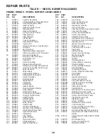
REPAIR PARTS

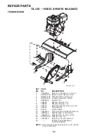
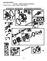
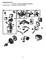
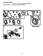
TILLER - - MODEL NUMBER 944.628653

ENGINE, BRIGGS -- MODEL NUMBER 121002-1380-B8

KEY    PART 
NO. NO. 

DESCRIPTION

KEY    PART 
NO. NO. 

DESCRIPTION

1 699510 Cylinder 

Assembly

399269 

Kit-Bushing/Seal (Magneto Side)

299819s 

Seal-Oil (Magneto Side)

5 797439 Head-Cylinder
7 698210 Gasket-Cylinder 

Head

11 790632  Tube-Breather
12 699485  Gasket-Crankcase
13 

699482 

Screw (Cylinder Head)

15 691686  Plug-Oil 

Drain

15A 691682 

Plug-Oil 

Drain

16 797070  Crankshaft
18 699696  Cover-Crankcase 
20 

692550 

Seal-Oil (PTO Side)

21 281658s  Cap-Oil 

Fill

22 

699478 

Screw (Crankcase Cover/Sump)

23 699488  Flywheel
24 222698s  Key-Flywheel
25 

795429 

Piston Assembly (Standard)


795430 

Piston Assembly (.020” Oversize)

26 

791969 

Ring Set (Standard)


793001 

Ring Set (.020” Oversize)

27 691866  Lock-Piston 

Pin

28 499423  Pin-Piston
29 690124  Rod-Connecting
30 791584  Dipper-Connecting 

Rod

32 

691664 

Screw (Connecting Rod) (Short)

32A 

695759 

Screw (Connecting Rod) (Long)

33 499642  Valve-Exhaust
34 795443  Valve-Intake
35 691304  Spring-Valve 

(Intake)

36 691304  Spring-Valve 

(Exhaust)

37 699661  Guard-Flywheel
40 692194  Retainer-Valve
45 690977  Tappet-Valve
46 693404  Camshaft
48 791518  Short 

Block

51 692555  Gasket-Intake
55 791848  Housing-Rewind 

Starter

58 693389  Rope-Starter
60 490652  Grip-Starter 

Rope

65 

699228 

Screw (Rewind Starter)

95 

691636 

Screw (Throttle Valve)

97 690024  Shaft-Throttle
98 398185  Kit-Idle 

Speed

104 691242 

Pin-Float 

Hinge

108 692567 

Valve-Choke

109 790624 

Shaft-Choke

117 690048 

Jet-Main 

(Standard)

118 

497315 

Jet-Main (High Altitude)

121 792006 

Kit-Carburetor 

Overhaul

122 795643 

Spacer-Carburetor

125 698474 

Carburetor

127 691739 

Plug-Welch

130 691181 

Valve-Throttle

133 398187 

Float-Carburetor

134 398188 

Kit-Needle/Seat

137 693981 

Gasket-Float 

Bowl

146 690979 

Key-Timing

155 797442 

Plate-Cylinder 

Head

161 790631 

Base-Air 

Cleaner

163 696024 

Gasket-Air 

Cleaner

186 692317 

Hose-Connector

187 

791766 

Line-Fuel (Cut to Required Length)

187A 791867 

Line-Fuel 

(Formed)

188 

699479 

Screw (Control Bracket)

190 

699220 

Screw (Fuel Tank)

192 797440 

Adjuster-Rocker 

Arm

209 691278 

Spring-Governor 

(Platinum)

209 

692571 

Spring-Governor (# 5 Hole)

219 693578 

Gear-Governor

220 

691724 

Washer (Governor Gear)

222 793107 

Bracket-Control

227 794367 

Lever-Governor 

Control

238 691300 

Cap-Valve

265 691024 

Clamp-Casing

267 

699492 

Screw (Casing Clamp)

276 271716 

Washer-Sealing

281 793122 

Panel-Control

300 693593 

Muffler

304 699598 

Housing-Blower

305 

699480 

Screw (Blower Housing)

306 795334 

Shield-Cylinder

307 

699483 

Screw (Cylinder Shield)

332 792723 

Nut 

(Flywheel)

333 796964 

Armature-Magneto

334 

699477 

Screw (Magneto Armature)

337 491055s  Plug-Spark
356 692390 

Wire-Stop

358 791797 

Gasket 

Set-Engine

365 699484 

Screw 

(Carburetor)

415 

693463 

Plug (Crankcase Cover)

445 

491588s 

Filter-Air Cleaner Cartridge

455 692591 

Cup-Flywheel

456 692299 

Plate-Pawl 

Friction

459 281505s  Pawl-Ratchet
505 

691251 

Nut (Governor Control Lever)

552 692346 

Bushing-Governor 

Crank

562 

691119 

Bolt (Governor Control Lever) 

597 

691696 

Screw (Pawl Friction Plate)

601 791850 

Clamp-Hose 

(Green)

608 795930 

Starter-Rewind

613 699209 

Screw 

(Muffler)

615 692576 

Retainer-Governor 

Shaft

616 692547 

Crank-Governor

619 

699230 

Screw (Cylinder Head Plate)

621 692310 

Switch-Stop 

(Brake)

632 693408 

Spring/Link-Mechanical 

Governor

633 

693867 

Seal-Choke/Throttle Shaft (Choke 
Shaft)

633A  691321 

Seal-Choke/Throttle Shaft (Throttle 
Shaft)

635 692076 

Boot-Spark 

Plug

663 

699206 

Screw (Control Panel)

676 796596 

Deflector-Muffler

Summary of Contents for 944.628653

Page 1: ...ules and Instructions Before Operating This Equipment MODEL NO 944 628653 OWNER S MANUAL Assembly Operation Maintenance Service and Adjustments Repair Parts 900 SERIES 24 INCH TINE WIDTH Sears Canada Inc Toronto Ontario M5B 2B8 434930 Rev 1 ...

Page 2: ... the controls and the proper use of the equipment Know how to stop the unit and disengage the controls quickly Never allow children to operate the equipment Never allow adults to operate the equipment without proper instruction Keep the area of operation clear of all persons par ticularly small children and pets PREPARATION Thoroughly inspect the area where the equipment is to be used and remove a...

Page 3: ...NIT IS EQUIPPED WITH AN INTERNAL COMBUSTION ENGINE AND SHOULD NOT BE USED ON OR NEAR ANY UNIMPROVED FOREST COVERED BRUSH COVERED OR GRASS COVERED LAND UNLESS THE ENGINE S EXHAUST SYSTEM IS EQUIPPED WITH A SPARK ARRESTER MEETING APPLICABLE LOCAL OR STATE LAWS IF ANY IF A SPARK ARRESTER IS USED IT SHOULD BE MAINTAINED IN EFFECTIVE WORKING ORDER BY THE OPERATOR SEE YOUR SEARS AUTHORIZED SERVICE CENTR...

Page 4: ...tion standing behind tiller handles Your new tiller has been assembled at the factory with exception of those parts left unassembled for shipping purposes To ensure safe and proper operation of your tiller all parts and hardware you assemble must be tightened securely Use the correct tools as necessary to insure proper tightness ASSEMBLY 2 Flange Locknuts 5 16 18 UNC 2 Lock Washer 5 16 2 Hex Nut 5...

Page 5: ...olumn onto handle mount Remove all packing from carton Secure handle column using two 2 carriage bolts and two 2 flange locknuts Tighten securely Cut away carton Route tine control cable s through plastic cable clip on handle mount NOTE Cables must not touch the muffler Cut cable ties securing tiller to skid Remove tiller from skid by pulling backwards Remove screws securing depth stake to skid an...

Page 6: ...or RECOIL STARTER HANDLE Used to start the engine THROTTLE CONTROL Used to control engine speed KNOW YOUR TILLER READ THIS OWNER S MANUAL AND SAFETY RULES BEFORE OPERATING YOUR TILLER Compare the illustrations with your tiller to familiarize yourself with the location of various controls and adjustments Save this manual for future reference These symbols may appear on your Tiller or in literature ...

Page 7: ...6 TO TRANSPORT CAUTION Before lifting or trans porting allow tiller engine and muffler to cool Disconnect spark plug wire Drain gasoline from fuel tank AROUND THE YARD Tip depth stake forward until it is held by the stake spring Push tiller handles down raising tines off the ground Push or pull tiller to desired location AROUND TOWN Disconnect spark plug wire Drain fuel tank Transport in upright p...

Page 8: ...ing engine When starting engine for the first time or if engine has run out of fuel it will take extra pulls of the recoil starter to move fuel from the tank to the engine Make sure spark plug wire is properly connected Place throttle control in FAST position Move choke control to full CHOKE position Grasp recoil starter handle with one hand and grasp tiller handle with other hand Pull rope out sl...

Page 9: ...ainfall and wind it may be advisable to till the soil at the end of the grow ing season to further condition the soil Soilconditionsareimportantforpropertilling Tineswill notreadilypenetratedry hardsoilwhichmaycontribute to excessive bounce and difficult handling of your tiller Hard soil should be moistened before tilling however extremely wet soil will ball up or clump during tilling Wait until t...

Page 10: ...proper air fuel mixture and help your engine run better and last longer BEFORE EACH USE Check engine oil level Check tine operation Check for loose fasteners LUBRICATION Keep unit well lubricated See LUBRICATION CHART LUBRICATION CHART 4 3 5 ª ª 4 3 3ª9 5ª 0 4 2 5 2ª3 26 HECKª NGINEª ILª EVEL HANGEª NGINEª IL ILª0IVOTª0OINTS NSPECTª IRª3CREEN NSPECTª3PARKª RRESTERª ª UFFLER LEANªORª2EPLACEª IRª LE...

Page 11: ...fins as contact may cause burns TO CHANGE ENGINE OIL See Figs 11 and 12 Determine temperature range expected before oil change All oil must meet API service classification SF SJ Be sure tiller is on level surface Oil will drain more freely when warm Catch oil in a suitable container Remove drain plug Tip tiller forward to drain oil After oil has drained completely replace oil drain plug and tighte...

Page 12: ...K PLUG Replace spark plugs at the beginning of each tilling sea son or after every 50 hours of use whichever comes first Spark plug type and gap setting are shown in PRODUCT SPECIFICATIONS on page 3 of this manual TRANSMISSION Once a season lubricate the right hand side gear case grease fitting with 1 oz of EP 1 Grease CLEANING Do not clean your tiller when the engine and transmission are hot We d...

Page 13: ...L TILLING See Fig 16 Assemble holes A in tine hubs to holes B in tine shaft tine_4 OUTER TINE HAIRPIN CLIP A B A B Fig 16 INNER TINE CLEVIS PIN NOTE When reassembling outer tines be sure right tine assembly marked R and left tine assembly marked L are mounted to correct side of tine shaft TINE OPERATION CHECK See Fig 18 WARNING Disconnectsparkplugwire fromsparkplugtopreventstartingwhile checking t...

Page 14: ... guard must be removed to service belt See TO RE MOVE BELT GUARD in this section of manual BELT REMOVAL Remove V belt from transmission pulley first and then from engine pulley BELT REPLACEMENT Install new V belt to engine pulley first then to trans mission pulley Be sure belt is positioned on inside groove of both pulleys inside all belt guides and rests on idler pulley CHECK TINE OPERATION See T...

Page 15: ...Inspect and replace belts if necessary See belt re placement instructions in the Service and Adjustments section of this manual Lubricate as shown in the Maintenance section of this manual Be sure that all nuts bolts and screws are securely fastened Inspect moving parts for damage breakage and wear Replace if necessary Touch up all rusted or chipped paint surfaces sand lightly before painting ENGI...

Page 16: ...ill and clean carburetor 6 Stale or dirty fuel 6 Empty fuel tank and refill with fresh gasoline 7 Water in fuel 7 Empty fuel tank and carburetor and refill tank with fresh gasoline 8 Clogged fuel tank 8 Remove fuel tank and clean 9 Spark plug wire loose 9 Connect and tighten spark plug wire 10 Dirty engine air screen 10 Clean engine air screen 11 Dirty clogged muffler 11 Clean replace muffler 12 C...

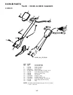
Page 17: ...07 Bolt RH SQNK 5 16 18 x 3 4 14 181476 Assembly Panel and Tube 19 188532 Lever Control Tine 20 188555 Pin Pivot 29 12000059 Retainer Ring 35 72010520 Bolt 5 16 18 x 2 1 2 36 73970500 Locknut Flange 5 16 18 unc 38 431332 Assembly Handle Column 39 181580 Clip NOTE All component dimensions given in U S inches 1 inch 25 4 mm KEY PART NO NO DESCRIPTION ...

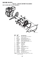
Page 18: ...8 139155 Spacer Split 9 165768X613 Guard Belt 10 109227X Pad Idler 11 9484R Clip Cable 12 9180R V Belt 13 12000028 Ring Retainer 14 151223 Sheave Transmisison 16 12000036 Ring Klip 17 STD541237 Nut Hex Jam 3 8 16 18 161806 Pulley Idler 19 175377 Arm Idler 20 STD523712 Bolt Hex Head 3 8 16 x 1 1 4 21 106968X Shaft Idler Arm 25 73350500 Nut Hex Jam 5 16 18 KEY PART NO NO DESCRIPTION NOTE All compone...

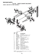
Page 19: ...pth Stake R H 9 122233X Stake Depth 10 326J Pin Clevis 11 74780628 Bolt Hex 3 8 16 x 1 3 4 13 1951J Support Depth Stake L H 15 5388J Spring Stake 16 121117X Bolt Shoulder 17 193851X613 Wheel 19 9190R Bracket Wheel 20 STD541437 Locknut Crown 3 8 16 21 74760516 Bolt Hex Head 5 16 18 x 1 22 STD541431 Locknut w insert 5 16 18 24 73970500 Nut Lock 5 16 18 25 19171416 Washer 17 32 x 7 8 x16 Ga KEY PART ...

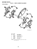
Page 20: ...5 4 mm REPAIR PARTS TILLER MODEL NUMBER 944 628653 TINE ASSEMBLY 1 156926 Tine Outer R H 2 3146R Retainer Spring Zinc 3 156924 Tine Inner R H 4 156923 Tine Inner L H 5 156925 Tine Outer L H 6 4929H Pin Clevis KEY PART NO NO DESCRIPTION 3 1 6 4 5 6 2 2 tine_ipb_3 ...

Page 21: ...ngine L H 11 187912 Bolt Shoulder 5 16 18 unc x 2 5 12 151222 Transmission 14 9173R Spacer Split 15 73970500 Nut Lock Hex Flange 5 16 18 unc 16 19091412 Washer 9 32 x 7 8 x 12 Ga 17 19092016 Washer 9 32 x 1 1 4 x 16 Ga 18 STD551125 Washer Lock 1 4 19 74610412 Bolt Hex 1 4 28 x 3 4 Gr 5 20 Engine See Breakdown 121002 1380 B8 KEY PART NO NO DESCRIPTION NOTE All component dimensions given in U S inch...

Page 22: ...425979 Decal Logo 3 435125 Decal Engine 4 425981 Decal Tine Shield 5 419833 Decal Cntrl Pnl Inst 6 110614X Decal Hand Placement 8 422972 Decal Tine Shield Warning 11 120076X Decal Warning Rotating Tines 12 425501 Decal Console 434930 Manual Owner s English 434931 Manual Owner s French 5 8 11 3 6 1 12 2 4 ...

Page 23: ...23 REPAIR PARTS TILLER MODEL NUMBER 944 628653 ENGINE BRIGGS MODEL NUMBER 121002 1380 B8 2 0 2 5 3 24 2 0 4 0 2 4 2 3 5 ...

Page 24: ...24 REPAIR PARTS TILLER MODEL NUMBER 944 628653 ENGINE BRIGGS MODEL NUMBER 121002 1380 B8 ...

Page 25: ...25 REPAIR PARTS TILLER MODEL NUMBER 944 628653 ENGINE BRIGGS MODEL NUMBER 121002 1380 B8 6 6 3 4 3 4 2 52 4 2 6 2 5 4 3 4 3 4 33 3 ...

Page 26: ...Welch 130 691181 Valve Throttle 133 398187 Float Carburetor 134 398188 Kit Needle Seat 137 693981 Gasket Float Bowl 146 690979 Key Timing 155 797442 Plate Cylinder Head 161 790631 Base Air Cleaner 163 696024 Gasket Air Cleaner 186 692317 Hose Connector 187 791766 Line Fuel Cut to Required Length 187A 791867 Line Fuel Formed 188 699479 Screw Control Bracket 190 699220 Screw Fuel Tank 192 797440 Adj...

Page 27: ...4 699480 Screw Rocker Cover Bottom 914A 797444 Screw Rocker Cover 951 790630 Lever Choke 957 795027 Cap Fuel Tank 958 698180 Valve Fuel Shut Off 968 791082 Cover Air Cleaner 972 697779 Tank Fuel 975 790559 Bowl Fuel 993 694088 Gasket Cylinder Head Plate 1005 692592 Fan Flywheel 1022 691890 Gasket Rocker Cover 1023 499924 Cover Rocker 1026 790287 Rod Push 1029 797443 Arm Rocker 1034 691343 Guide Pu...

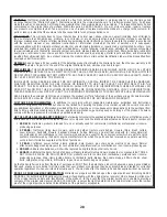
Page 28: ...n SUCH REMEDY SHALL BE YOUR SOLE AND EXCLUSIVE REMEDY FOR ANY BREACH OF WARRANTY CUSTOMER RESPONSIBILITIES In additional to complying with all suggested maintenance guidelines and instructions customers obligations shall include but shall not be limited to operating the product in accordance with the owner s manual or any additional instructions or information provided at the time of purchase or i...

Page 29: ...29 SERVICE NOTES ...

Page 30: ...30 SERVICE NOTES ...

Page 31: ...31 SERVICE NOTES ...

Page 32: ...02488 03 09 10 JA Printed in the U S A ...

Reviews: