background image

12

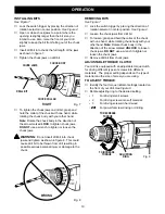
CHUCK REMOVAL

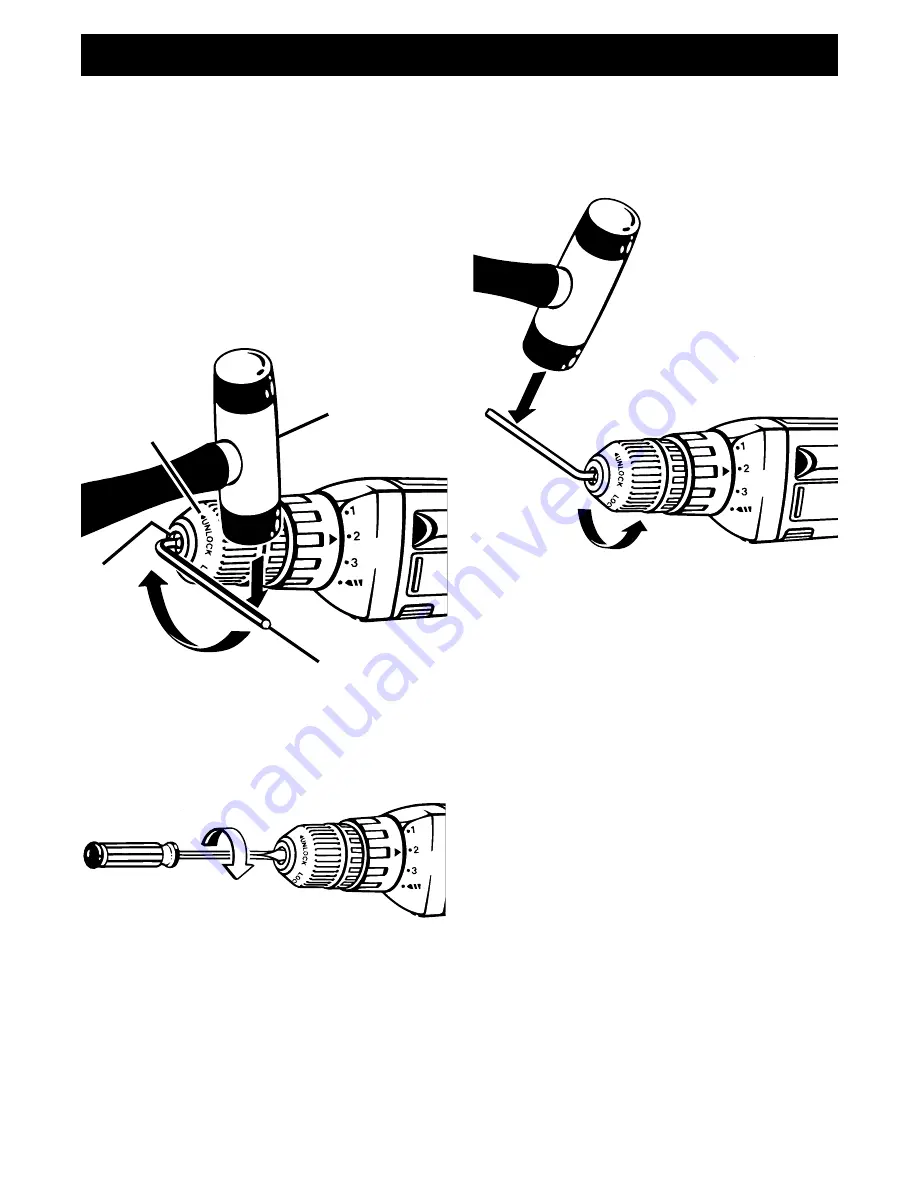
See Figures 13, 14, and 15.

The chuck must be removed in order to use some
accessories. To remove:

Lock the switch trigger by placing the direction of
rotation selector in center position.

Insert a 5/16 inch or larger allen wrench (hex key
wrench) into the chuck of your drill and tighten the
chuck jaws securely.

Tap the allen wrench sharply with a mallet in a
clockwise direction. See

 Figure 13. This will

loosen the screw in the chuck for easy removal.

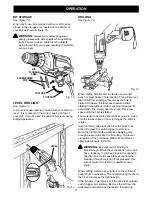
Insert allen wrench in chuck and tighten chuck
jaws securely. Tap sharply with a mallet in a
counterclockwise direction. This will loosen chuck
on the spindle. It can now be unscrewed by hand.
See Figure 15.

OPERATION

ALLEN WRENCH

MALLET

Fig. 13

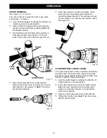
Open chuck jaws and remove allen wrench.
Remove the chuck screw by turning it in a clock-
wise direction. 

See Figure 14. Note: The screw

has left hand threads.

Fig. 14

Fig. 15

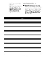
TO RETIGHTEN A LOOSE CHUCK

The chuck may become loose on spindle and develop
a wobble. Also, the chuck screw may become loose
causing the chuck jaws to bind and prevent them from
closing. To tighten, follow these steps:

Lock the switch trigger by placing the direction of
rotation selector in center position.

Insert allen wrench into chuck and tighten chuck
jaws securely. Tap allen wrench sharply with a
mallet in a clockwise direction. This will tighten
chuck on the spindle.

Open the chuck jaws and remove allen wrench.

Tighten the chuck screw. Note: The chuck screw
has left hand threads.

CHUCK

JAWS

KEYLESS

CHUCK

Summary of Contents for 973.274960

Page 1: ... No 973 274960 CAUTION Read and follow all Safety Rules and Operating Instruc tions before first use of this product 972000 435 3 98 Sears Roebuck and Co Hoffman Estates IL 60179 USA Owner s Manual Save this manual for future reference SAFETY OPERATION MAINTENANCE PARTS LIST ...

Page 2: ...This warranty gives you specific legal rights and you may also have other rights which vary from state to state Sears Roebuck and Co Dept 817WA Hoffman Estates IL 60179 INTRODUCTION SPECIFICATIONS Chuck Capacity 3 8 in Motor 9 6 Volts DC Charger Rating 120 Volts 60 Hz AC Only No Load Speed 0 600 RPM Switch Variable Speed Reversible Charge Rate 1 1 2 Hour Your drill driver has many features for mak...

Page 3: ...May be used in conjunction with other symbols or pictographs WARNING Failure to obey a safety warning can result in serious injury to yourself or to others Always follow the safety precautions to reduce the risk of fire electric shock and personal injury CAUTION Failure to obey a safety warning may result in property damage or personal injury to yourself or to others Always follow the safety preca...

Page 4: ... your battery tool or when changing accessories USE ONLY THE CHARGER PROVIDED WITH YOUR BATTERY TOOL Do not substitute any other charger Use of another charger could cause batteries to explode causing possible serious injury DO NOT PLACE BATTERY TOOLS OR THEIR BATTERIES NEAR FIRE OR HEAT They may explode DO NOT CHARGE BATTERY TOOL IN A DAMP OR WET LOCATION Your battery tool should be charged in a ...

Page 5: ... Wide Vision Safety Mask for use over eyeglasses or standard safety glasses with side shields available at Sears Retail Stores WARNING Cord Length Feet 25 50 100 150 Cord Size AWG 16 16 16 14 Note AWG American Wire Gage IMPORTANT INFORMATION FOR RECHARGING HOT BATTERIES When using your drill driver continuously the batteries in your battery pack will become hot You should let a hot battery pack co...

Page 6: ...f dropping your drill driver Place one hand through the wrist strap when carrying tool WARNING The use of attachments or accessories not listed might be hazardous ACCESSORIES FEATURES WARNING If any parts are missing do not operate tool until the missing parts are replaced Failure to do so could result in possible serious personal injury Chuck Key Item No 2058 Chuck Item No 2975 Keyless Chuck Item...

Page 7: ...ights on charger will come on This indicates charger is in soft start mode and should switch to fast charge mode within 5 minutes When charger is in fast charge mode the red light will come on If after a period of 15 minutes the yellow and green lights remain on remove battery pack wait 1 minute and re insert batery pack in charger If the yellow and green lights continue to remain on after an addi...

Page 8: ...ches snap in place properly Improper assembly of battery pack can cause damage to internal components TO REMOVE BATTERY PACK Lock switch trigger on your drill by placing the direction of rotation selector in center position See Figure 2 Locate latches on end of battery pack and depress to release battery pack from your drill See Figure 3 Remove battery pack from your drill Fig 3 BATTERY PACK LATCH...

Page 9: ...LOCK TIGHTEN Fig 4 REVERSIBLE See Figure 4 This tool is reversible The direction of chuck rotation is controlled by a selector located above the switch trigger With the drill held in normal operating position the direction of rotation selector should be positioned to the left of the switch for drilling The drilling direction is reversed when the selector is to the right of the switch When the sele...

Page 10: ...E TORQUE CLUTCH Your drill is equipped with an adjustable torque clutch for driving different types of screws into different materials The proper setting depends on the type of material and the size of screw you are using TO ADJUST TORQUE Identify the four torque indicator settings located on the front of your drill See Figure 9 Rotate adjusting ring to the desired setting 1 For driving small scre...

Page 11: ...ed To accomplish this simply operate your drill at a low speed until the hole is started The material to be drilled should be secured in a vise or with clamps to keep it from turning as the drill bit rotates Hold tool firmly and place the bit at the point to be drilled Depress the switch trigger to start tool Move the drill bit into the workpiece applying only enough pressure to keep the bit cutti...

Page 12: ...rewed by hand See Figure 15 OPERATION ALLEN WRENCH MALLET Fig 13 Open chuck jaws and remove allen wrench Remove the chuck screw by turning it in a clock wise direction See Figure 14 Note The screw has left hand threads Fig 14 Fig 15 TO RETIGHTEN A LOOSE CHUCK The chuck may become loose on spindle and develop a wobble Also the chuck screw may become loose causing the chuck jaws to bind and prevent ...

Page 13: ...l as workpiece Only the parts shown on parts list page fifteen are intended to be repaired or replaced by the customer All other parts should be replaced by a qualified service technician at an authorized service facility WARNING Do not attempt to modify this tool or create accessories not recommended for use with this tool Any such alteration or modification is misuse and could result in a hazard...

Page 14: ...e recycling and or disposal options WARNING Upon removal cover the battery pack s terminals with heavy duty adhesive tape Do not attempt to destroy or disassemble battery pack or remove any of its components Nickel cadmium batteries must be recycled or disposed of properly Also never touch both terminals with metal objects and or body parts as short circuit may result Keep away from children Failu...

Page 15: ...repair parts PARTS LIST PARTS LIST Key Part No Number Description Quan 1 616478 003 Screw Special 1 2 973094 001 Chuck Item No 20988 1 3 970832 000 Screw 2 4 970833 000 Washer 1 5 970355 000 Clutch Cap 1 6 970835 000 Clutch Ring 1 7 970836 000 Spring 1 8 970837 000 Washer Shim as needed 1 9 967216 004 Wrist Strap 1 10 970813 002 Battery Pack Item No 11108 1 11 974511 002 Battery Charger Item No 11...

Page 16: ...BACK PAGE ...

Reviews: