background image

Summary of Contents for BRUSHWACKER 316.74520

Page 1: ...4520 _ WARNING Before using this product read this manual and follow all its Safety Rules and Operating Instructions Safety Assembly Operation Maintenance Parts List Espa_ol Save this manual for future reference Sears Roebuck and Co Hoffman Estates IL 60179 USA OPERATOR S MANUAL PART NO 769 00066 PRINTED IN U S A 2 02 Revl ...

Page 2: ...ODUCT CONTAINS CHEMICALS KNOWN TO THE STATE OF CALIFORNIA TO CAUSE CANCER BIRTH DEFECTS OR OTHER REPRODUCTIVE HARM NOTE For users on U S Forest Land and in the states of California Maine Oregon and Washington All U S Forest Land and the state of California Public Resources Codes 4442 and 4443 Oregon and Washington require by law that certain internal combustion engines operated on forest brush and...

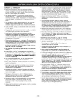
Page 3: ...cked chipped or damaged in any way Do not operate the unit with loose or damaged parts Use only 0 095 in 2 41 mm diameter genuine Craftsman replacement line Never use metal reinforced line wire or rope etc These can break off and become dangerous projectiles Be aware of the risk of injury to the head hands and feet Clear the area to be cut before each use Remove all objects such as rocks broken gl...

Page 4: ... before repairing damage Do not operate the unit with loose or damaged parts Do not operate unit with a bent cracked or dull blade Discard blades that are bent warped cracked or broken Stop and switch the engine to OFF for maintenance repair or for changing the cutting attachment or other attachments Use only genuine Craftsman replacement parts when servicing this unit These parts are available fr...

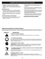
Page 5: ...tructions SAVE THESE INSTRUCTIONS SAFETY AND INTERNATIONAL SYMBOLS This operator s manual describes safety and international symbols and pictographs that may appear on this 3roduct Read the operator s manual for complete safety assembly operating and maintenance and repair information SYMBOL MEANING SAFETY ALERT SYMBOL ndicates danger warning or caution May be used with other symbols O READ OPERAT...

Page 6: ... or STOP SHARP BLADE S WARNING There is a sharp blade on the cutting attachment shield To prevent serious injury do not touch edge Do not touch the edges of the 44 tooth saw blade Wear gloves BRUSHCUTTERS Replace Dull Blade s Do not sharpen the brush blade s Sharpening the blade s can cause the blade tip to break off while in use this can result in severe personal injury TRIMMER BRUSHCUTTER SAFETY...

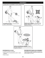
Page 7: ...18 Cutting Attachment Shield Locking Rod Tool 3 Screws 1 4 20 x 1 2 for Cutting Attachment Shield Shoulder Harness Blade Nut Operator s Manual Bottle of Oil 4 Tooth Blade 44 Tooth Blade 7 ...

Page 8: ...o 1 2 inch in diameter I i iiii ii i i_ii i i iii I_ u 44 TOOTH BLADE used for cutting grass weeds and woody brush up to 2 inches in diameter CARTON CONTENTS Brushcutter Trimmer Assist Handle with upper and middle clamps attached Hardware Pack ASSEMBLY INFORMATION To ensure safe and proper operation of your unit all parts and hardware you assemble must be tightened securely 8 ...

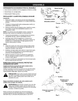
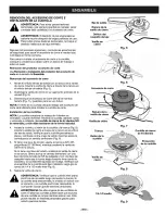
Page 9: ...ecal touches the clamp assembly Fig 2 8 While holding the unit in the operating position Fig 3 position the assist handle to the location that provides you the best grip 9 Tighten the clamp screws evenly until the assist handle is secure REMOVING AND INSTALLING CUTTING ATTACHMENT SHIELD Install the cutting attachment shield when using the unit as a grass trimmer Install the cutting attachment shie...

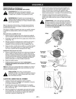
Page 10: ...down and reinstalling it The 44 tooth saw blade is NOT reversible and should be installed only as shown 4 Install the blade blade retainer and lock nut Fig 8 Insert the locking rod through the slot into the outout shaft hole Make sure that the blade stays flat and centered against the output shaft while tightening the lock nut counterclockwise Fig 9 5 If you have a torque wrench tighten the lock n...

Page 11: ...ighten securely NOTE The blade retainer must be installed on the output shaft in the position shown for the cutting attachment to work correctly 6 Remove the locking rod 7 Install the cutting attachment shield See Removing and Installing Cutting Attachment Shield in the Assembly section CAUTION To prevent serious personal injury and damage to the unit the cutting attachment shield must be used whe...

Page 12: ...rting the engine PRIMER BULB removes air from the fuellines and fills the carburetor with fuel THROTTLE CONTROL controls engine speed for various cutting conditions ASSIST HANDLE used to hold the unit during operation CUTTING ATTACHMENT SHIELD protects operator from thrown debris Contains line cut off blade to make sure the line is not extended beyond its proper length Cutting attachment shield mu...

Page 13: ...resh unleaded gasoline that is less than 60 days old Oil and Fuel Mixing Instructions Thoroughly mix the proper ratio of unleaded gasoline with 2 cycle engine oil in a separate fuel can 40 1 Do not mix them directly in the engine fuel tank Use 3 2 oz 95ml of 2 cycle engine oil per one gallon of unleaded gasoline to achieve a 40 1 fuel oil ratio Use of Blended Fuels If you choose to use a blended f...

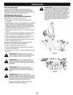
Page 14: ...t clipped to the unit prior to starting See To Adjust the Shoulder Harness in the Assembly section 1 Move On Off Stop Control to ON Fig 16 2 Fully press and release primer bulb 5 to 7 times Fuel should be visible in the bulb Fig 16 If fuel hasn t entered the bulb press three 3 more times or until it does 3 Move choke control Fig 16 to CHOKE H A 4 Squeeze throttle control and pull starter rope Fig ...

Page 15: ...the engine To release additional line lightly bump the cutting attachment on the ground while operating the trimmer at high speed Fig 9 NOTE Line release becomes more difficult as cutting line becomes shorter Always keep the trimming line extended to its full cutting length Each time the head is bumped about 1 inch 25 4 mm of line is released A blade in the guard will cut the line to the proper le...

Page 16: ...l to be cut from your right to your left Fig 22 When making the return swing avoid the material you just cut _lb WARNING Always wear eye hearing foot and body protection to reduce the risk of injury when operating this unit WARNING Do not sharpen the brush blade s Sharpening a blade can cause the blade tip to break off while in use This can re sult in severe personal injury _ WARNING To avoid seri...

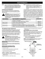
Page 17: ...ark arrestor screen for clogging Page 22 or obstruction to assure maximum performance levels GENERAL RECOMMENDATIONS WARNING To prevent serious injury never perform maintenance on the unit while it is running Shut off the unit and allow it to cool down before doing any maintenance Disconnect the spark plug wire to prevent the Unit from starting The warranty on this line trimmer does not cover item...

Page 18: ...OTE The choke lever must be in the PARTIAL choke position B Eig 23 to install the air filter muffler cover 2 Insert the four 4 screws into the holes in the air filter muffler cover Fig 23 and tighten Do not over TO REPLACE SPARK PLUG Use a Champion RDJ7Y spark plug or equivalent Correct air gap is 0 020 in 0 50 ram Remove plug after every 25 hours of operation and check its condition Fig_28 1 Stop...

Page 19: ... It is very important to use the correct size line Use line with a diameter of 0 095 inch 2 41 mm The engine may overheat and fail if you use a size other than specified Removing the Reel 1 Hold the reel housing with one hand and unscrew the Bump Knob TM clockwise Fig 29 Inspect the captured bolt inside the Bump Knob to make sure it moves freely Replace the Bump Knob if it is damaged 2 Remove the ...

Page 20: ... PREWOUND REEL 1 Hold the reel housing with one hand and unscrew the Bump Knob clockwise Fig 29 Inspect the bolt inside the Bump Knob to make sure it moves freely Replace the Bump Knob if damaged 2 Remove the old reel from the reel housing Fig 29 3 Remove the spring from the old reel Fig 29 4 Use a clean cloth to clean the inner surface of the reel housing Fig 39 5 Place the spring in the new reel...

Page 21: ...s to prevent serious personal injury If after checking the fuel mixture and cleaning the air filter the engine still will not idle adjust the idle speed screw as follows 1 Start the engine and let it run at a high idle for a minute to warm up 2 Release the throttle trigger and let the engine idle If the engine stops insert a small phillips or flat blade screwdriver into the hole in the air filter ...

Page 22: ...m the muffler 4 5 6 7 Clean the spark arrestor screen with a wire brush Replace it if it is damaged or if you are unable to clean it thoroughly Reinstall the spark arrestor screen by laying it on top of the hole on the bottom of the muffler The screen s bubble goes over the hole and not inside it Make sure the edges of the spark arrestor screen fit flat against the muffler Place the inner deflecto...

Page 23: ... can add a fuel stabilizer to your fuel NEVER add fuel stabilizer directly to the unit s fuel tank 4 Allow the engine to cool Remove the spark plug and put about 1 oz 30 ml of any high quality motor oil or 2 cycle oil into the cylinder Pull the starter rope slowly to distribute the oil Reinstall the spark plug NOTE Remove the spark plug and drain all of the oil from the cylinder before attempting ...

Page 24: ...b fully and slowly 5 7 times Fuel should be visible in the bulb Replace spark plug Clean or replace spark arrestor Use starting procedure WITHOUT USING CHOKE Drain fuel tanWadd fresh fuel mixture Drain fuel tanWadd fresh fuel mixture Clean or replace air filter Adjust carburetor Stop engine and clean cutting attachment Drain fuel tanWadd fresh fuel mixture Clean or replace air filter Clean or repl...

Page 25: ... 25 ...

Page 26: ...onsibilities you should call 1 800 827 6655 Manufacturer s Warranty Coverage The warranty period begins on the date the engine or equipment is delivered to the retail purchaser The manufacturer warrants to the initial owner and each subsequent purchaser that the engine is free from defects in material and workmanship which cause the failure of a warranted part for a period of two years Repair and ...

Page 27: ...Fuel Cap Assembly Fuel Return Line Fuel Line Assembly Front Mounting Pad Shroud Assembly Shroud Screw Shroud Extension and Stand Flywheel Assembly Spacer Recoil Pulley Assembly Recoil Spring Pulley Retainer Assembly Rope Guide Pull Handle Rope Starter Housing Assembly includes 28 35 Item 35 36 37 38 39 46 41 42 43 44 45 46 47 48 49 5O 51 52 53 Part No 791 181862 791 182368 791 182369 791 153592 79...

Page 28: ...box Mounting Hardware 23 791 145569 Anti Rotation Screw 24 791 147492 Blade Shield Shield Mount 25 791 182196 Blade Driver 26 791 683304 Shield Mounting Screw 27 753 1191 Shield and Blade Assembly includes 28 28 791 682061 Blade Assembly 29 791 147490 Retaining Washer 30 791 612483 Spool Shaft 31 791 683301 Outer Spool and Eyelet Assembly 32 791 612026 Retainer 33 791 610636B Sprin 9 34 791 147495...

Page 29: ...74520 Seguridad Ensamble Operacibn Mantenimiento ADVERTENCIA antes de usar este producto lea este manual y siga sus Reglas de seguridad e Instrucciones de operacibn Guarde este manual para referencia futura Sears Roebuck and Co Hoffman Estates IL 60179 USA MANUAL DEL OPERADOR PARTE N 769 00066 IMPRESO EN LOS EE UU 2 02 Revl E1 ...

Page 30: ...DE ESTE PRODUCTO CONTIENEN SUBSTANCIAS QUJMICAS QUE EL ESTADO DE CALIFORNIA CONOCE COMO CAUSANTES DE CANCER DEFECTOS DE NACIMIENTO U OTROS DAI_IOS REPRODUCTIVOS NOTA Para los usuarios en tierras forestales de los EE UU y en los estados de California Maine Oregon y Washington Toda la tierra forestal de EE UU y del estado de California C6digos de Recursos PQblicos 4442 y 4443 Oregon y Washington req...

Page 31: ...scadas o daSadas de cualquler moao No opere esta un_eaa con 3ar_es flojas ni daSadas Use s61o linea de reemplazo Craftsman genuina de 0 095 pulgadas 2 41mm de di metro Nunca use linea reforzada con metal cable o soga e_c ya que pueden romperse convertlrse en proyectiles peligrosos Tenga en cuenta el nesgo de lesiones en la cabeza las manos y los pres Limpie el _rea de corse antes de cada uso Saque...

Page 32: ...e Si goipea o se enreda con algQn objeto extrafio apague el motor de inmediato y verifique si hay daSos No opere la unidad antes de reparar los daSos No opere la unidad si tiene piezas flojas o daSadas No opere la unidad con una cuchilla torcida rajada o desafilada Deseche las cuchillas que est6n torcidas encorvadas rajadas o rotas Apague el motor para realizar todo el mantenimiento reparaciones o...

Page 33: ...s Si le presta esta unidad a alguien pr6stele tambi6n estas instrucciones GUARDE ESTAS INSTRUCCIONES S MBOLOS DE SEGURIDAD E INTERNACIONALES Este Manual del Operador describe los simbolos y fJguras ee seguridad e _nternac_onales que pueden aparecer en este producto Lea e Manual del Operador para obtener informaci6n correcta acerca de la seguridad ensamble operaci6n y mantenimiento y reparac_on SJM...

Page 34: ...DIDO Y APAGADO APAGADO o PARADO CUCHILLA AFILADA ADMERTENCIA El protector accesorio de corte contiene una cuchilla afilada Para evitar graves lesiones personales no toque la cuchilla No toque los bordes de la cuchilla de sierra de 44 dientes Utilice guantes CORTADORAS DE MALEZA Cambie la s cuchUla s desafilada s No afile la s cuchilla s de corte El afilar la cuchilla puede causar que la punta de l...

Page 35: ... 18 Varilla de cierre 3 Tornillos 1 4 20 x 1 2 para el protector accesorio de corte Arn_s para el hombro Manual del operador Cuchilla de 4 dientes Tuerca de la cuchina tamat_oreal Botella de aceite Cuchilla de sierra de 44 dientes E7 ...

Page 36: ...metro CUCHILLA DE SIERRA DE 44 DIENTES se usa para cortar cesped hierbas y arbustos lefiosos de hasta 2 pulgadas de di metro CONTENIDO DE LA CAJA Cortadora de malezas Recortador Manija auxiiiar con ias abrazaderas superior y media colocadas Bolsa de piezas INFORMACI _N ACERCA DEL ENSAMBLE Para asegurar una operaci6n segura y correcta de su unidad todas las partes y piezas que ensamble deben estar ...

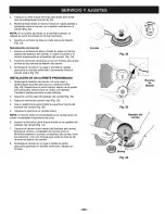
Page 37: ... o linea blanca de la calcomania toque el ensamble de abrazaderas Fig 2 8 Mientras sostiene la unidad en posici6n de operaci6n Fig 3 coloque la manija auxiliar en la posici6n que le brinde el mejor agarre 9 Ajuste los tornillos de la abrazadera en forma pareja hasta que la manija auxiliar est6 firme REMOCION E INSTALACION DEL PROTECTOR ACCESORIO DE CORTE Inetale el protector accesorio de corte cua...

Page 38: ...ble y sblo debe inetalarse de la forrna indicada 4 Instale la cuchilla el ret6n de la cuchilla y la tuerca Fig 8 Inserte la varilla de cierre a trav6s de la ranura en el orificio del eje de salida Verifique que la cuchilla permanezca plana y centrada contra el eje de salida mientras ajusta la contratuerca en sentido antihorario Fig 9 5 Si tiene una Ilave de torsi6n ajuste la tuerca a 325 335 pulg ...

Page 39: ... salida Ajuste bien 6 Saque la varilla de cierre 4 5 Ajuste el ames para el hombro para darle equilibrio de modo que el accesorio de corte quede nivelado con el suelo Un ames para el hombro bien ajustado debe sostener todo el peso de la unidad dejando sus brazos y manos libres para guiar y controlar el movimiento de corte Extienda el ames tirando de la correa hacia abajo y subiendo la hebilla Acor...

Page 40: ...rae el aire de las tuberias del y Ilena el carburador con combustible la velocidad del motor para diversas condiciones de corte MANIJA AUXlMAR se usa para sostener la unidad durante la operaci6n PROTECTOR ACCESORIO DE CORTE protege al operad0r de los residuos que salen despedidos Contiene la cuchilla coRadora de linea para verificar que la linea no ee extienda m s all de la Iongitud adecuada El pr...

Page 41: ...su manua de 0perador 2 Use un aditivo especial 3 Siempre agite la mezcla de combustible antes de alimenta_ la unidad 4 Drene e tanque y haga funcionar el motor en seco antes de guardar la unidad Uso de un estabilizador de combustible Si utiliza una marca de aceite que no sea Craftsman el uso de un estabilizador impedira la corrosi6n y reducir la formaci6n de un deposito de goma Agregue 0 8 onzas 2...

Page 42: ...o OFF Fig 15 INSTRUCCIONES DE ENCENDIDO NOTA Mezcle la gasolina con el aceite proporci6n de 40 1 Vea Instrucciones de mezcla de aceite y combustible en la secci6n de Operaci6n Llene su unidad con la mezcla de aceite y gasolina y coldquela sobre el piso para comenzar Fig 17 NOTA AI usar el arn6s para el hombro t6ngalo puesto y ajustado pero no abrochado a la unidad antes de arrancar Yea Ajuste del ...

Page 43: ...nea golpee ligeramente la cabeza contra el piso mientras opera la recortadora a alta velocidad Fig 19 r NOTA A medida que la linea se acorta es m s dificil soltarla Mantenga siempre la linea de core extendida en su maxima Iongitud de core Cada vez que golpea la cabeza se suelta aproximadamente 1 pulgada 25 4 mm de line Una cuchilla ubicada en la proteccidn cortar la linea en su Iongitud adeeuada s...

Page 44: ...d de derecha a izquierda hacia el material que se va a cortar Fig 22 En el movimiento de retomo no toque el material que acaba de cortar _ ADVERTENCIA Prot6jase siempre ia vista los oidos los pies y el cuerpo a fin de reducir el riesgo de sufrir lesiones al hacer uso de esta unidad ADVERTENCIA No afile la cuchilla cortadora Si afila la s cuchilla s la punta puede desprenderse durante su uso Esto p...

Page 45: ... limpielo P gina E22 Inspeccione la condici6n y la separaci6n de la bujia de encendido P gina E18 Cada 50 horas Inspeccione si la lumbrera de escape y la rejilla del parachispas est n P gina E22 tupidas u obstruidas para garantizar los niveles mAximos de rendimiento RECOMENDACIONES GENERALES La garantia de este recottador de linea no cubre los elementos aue han sido sometidos al abuso o negligenci...

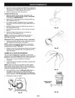
Page 46: ... filtro de aire silenciador sobre la pare postenor del carburador y silenciador NO A La palanca del obturador debe estar en la posici6n de obturacion parcial PARTIAL B Fig 23 para instalar la cubierta del filtro de aire silenciador 2 Inserte los cuatro 4 tornillos en los orificios de la cubierLa del filtro de aire silenciador Fig 23 y ajt3stelos No los ajuste demas_ado CAMBIO DE LA BUJIA DE ENCEND...

Page 47: ...que use el tamaSo de linea correcto Use linea con un di metro de 0 095 pulgadas 2 41 ram Si usa otra linea que la indicada el motor puede recalentarse y fallar Remocibn del carrete 1 2 3 Sostenga el bastidor del carrete con una mano y desenrosque la perilla percusiva en sentido horario Fig 29 Inspeccione el pemo cautivo dentro de la perilla percusiva para verificar que se mueva con libertad Cambie...

Page 48: ...n una mano y desenrosque la perilla percusiva en sentido horario Fig 29 Inspeccione el perno cautivo dentro de la perilla percusiva para verificar que se mueva con libertad Cambie la perilla percusiva si est daSada 2 Saque el carrete viejo del bastidor del carrete Fig 29 3 Saque el resorte del carrete viejo Fig 29 4 Use un paso limpio para limpiar la superficie interna del bastidor del carrete Fig...

Page 49: ...s personales Si luego de verificar la mezcla del combustible y limpiar el filtro de aire el motor at n no funciona en minima ajuste el tomillo de velocidad enta de la siguiente manera 1 Arranque el motor y deje que funcione en marcha r pida durante un minuto para que se caliente 2 Suelte el gatillo del regulador y deje que el motor funcione en marcha lenta Si el motor se para inserte un pequeSo de...

Page 50: ...a del parachispas con un cepillo de cerdas metalicas C mbiela siesta da5ada o si no la puede limpiar completamente Reinstale la rejila del parachispas colocandola enclma del orificio de la parte inferior del silenciador La parte abombada de la rejilla va enclma del orificio y no dentro del mismo AsegQrese de que los bordes de la rejilla del parachispas encajen en forma plana contra el silenciador ...

Page 51: ...bustible No agregue NUNCA un estabilizador de combustible directamente ee el tanque de combustible de la ueidad 4 Espere que el motor se enfrie Retire la bujia de encendido y coloque alrededor de 1 onza 30 ml de cualquier aceite de buena calidad para motor de 2 ciclos dentro del ciliedro Tire de la cuerda de arranque lentamente para esparcir e aceite Vuelva a instalar la bujia de encendid0_ NOTA R...

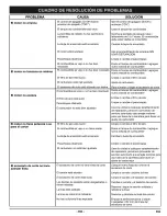
Page 52: ... total y lentamente de 5 a 7 veces El combustible debe estar visible en la bombilla Cambie la bujia de encendido Use el procedimiento de arranque SIN USAR OBTURACION Limpie o cambie el parachispas Drene el tanque de combustible agregue nueva mezcla de combustible Drene el tanque de combustible agregue nueva mezcla de combustible Limpie o cambie el filtro de aire Ajuste el carburador Pare el motor ...

Page 53: ... E25 ...

Page 54: ... E26 ...

Page 55: ... responsabilidades de su garantfa debe Ilamar al 1 800 827 6655 Cobertura de la Garantia del Fabricante El perfodo de garantfa empieza en la fecha que el motor o equio se le entrega al comprador al detalle El fabricante le garant_zaal propierario original y a cada comprador postenor que el motor no tiene defectos en cuanto a su material omano de obra los cuales causen lafalla de una pieza garantiz...

Page 56: ...s pieces For the repair or replacement parts you need Call 7 am 7 pm 7 days a week 1 800 366 PART 1 808 388 7278 Para ordenar piezas con entrega a domicilio 1 800 659 7084 For the location of a Sears Parts and Repair Center in your area Call 24 hours a day 7 days a week 1 800 488 1222 For information on purchasing a Sears Maintenance Agreement or to inquire about an existing Agreement Call 9 am 5 ...

Reviews: