


page 7
black
black
white
white
blue
black supply wire
ground
(green
or bare)
white supply wire
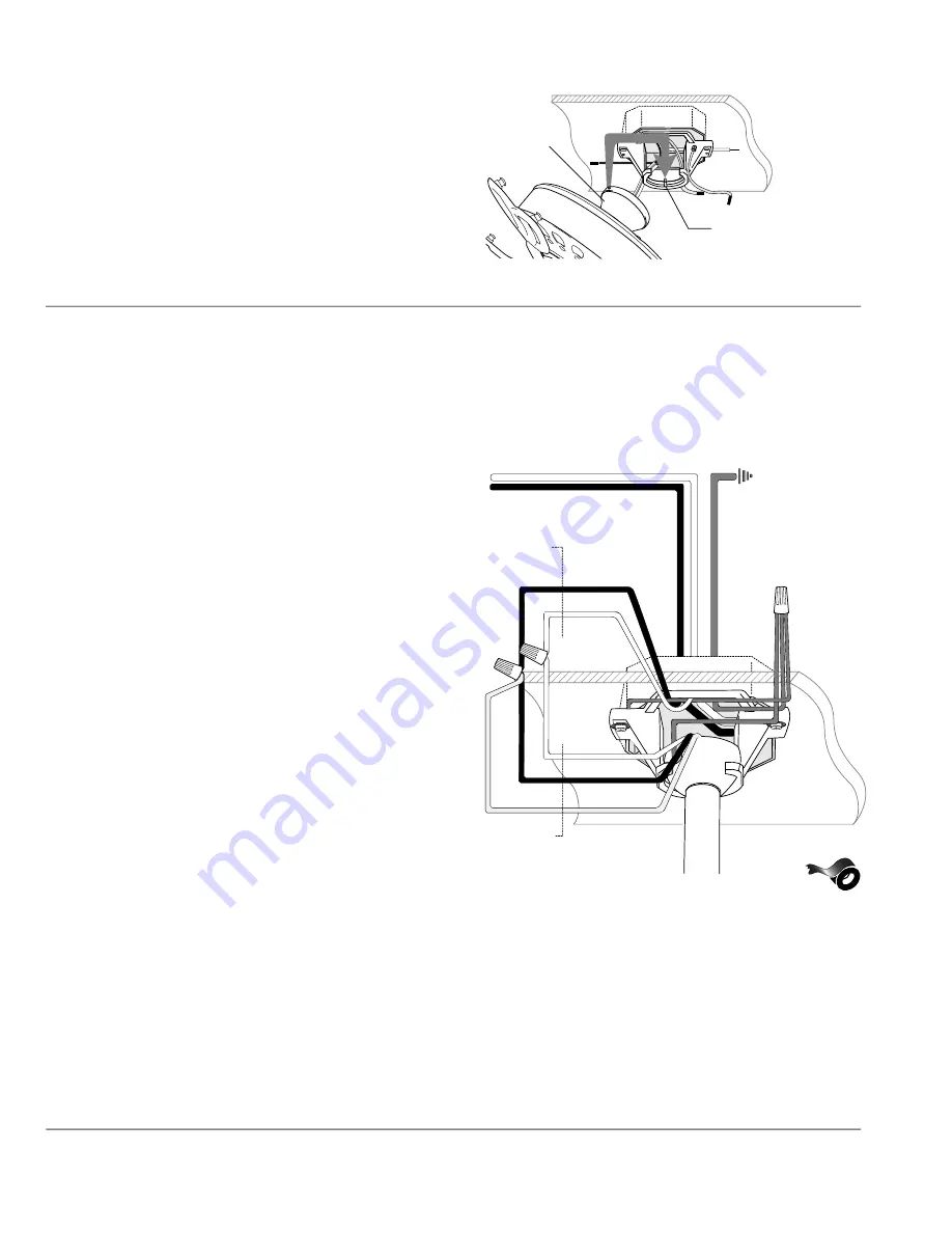
7. Wiring.
WARNING
: Turn off circuit breakers to
current fixture from breaker panel and be
sure switch is turned to the OFF position.
CAUTION
: Be sure outlet box is properly
grounded and that a ground (
GREEN
or Bare)
wire is present.
Make sure all electrical connections comply
with Local Codes or Ordinances and the
National Electrical Code. If you are unfamiliar
with electrical wiring or if the house/building
wires are different colors than those referred
to in the instructions below, please use a
qualified electrician.
When downrod is secured in place on the
hanging bracket, electrical wiring can be
made
as follows:
Connect
BLACK
and
BLUE
wires from fan
to
BLACK
wire from ceiling with wire
connector provided.
Connect
WHITE
wire from fan to
WHITE
wire from ceiling with wire connector
provided. Connect all
GROUND
(
GREEN
)
wires together from fan to
BARE
/
GREEN
wire from ceiling with wire connector
provided.
If you intend to control the fan light with a
separate light switch, connect
BLUE
wire
from fan to the
BLACK
(or
RED
) supply
from the independent switch.
*Wrap each wire connector separately with
electrical tape as an extra safety measure.
This fan is remote control adaptable (remote
control sold separately).
*
from
ceiling
from fan
ground
(green or bare)
wire
connector
wire
connectors
6. Fan Assembly (flushmount).
(cont.)
canopy
motor housing
hanging bracket tab
To prepare the fan for wiring, hang fan
onto hanging bracket by sliding the
canopy over the hanging bracket tab. (Use
one of the non-slotted holes on the rim of
the canopy to do so.)
[
Refer to
diagram 3
.
]
diagram 3


