background image

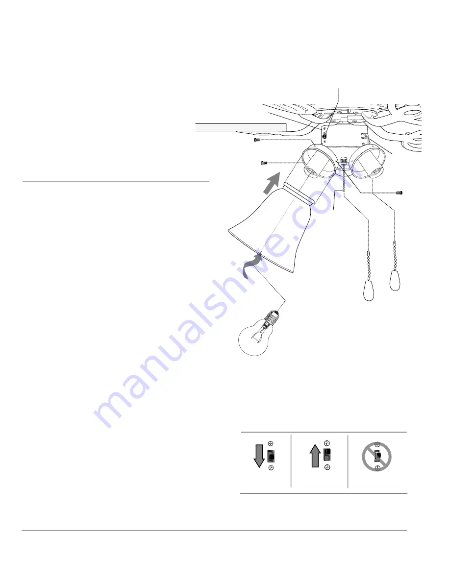
10. Light Kit Assembly.

page 9

glass shade

bulb

light kit fitter

11. Testing Your Fan.

switch housing

pull chain
extensions

 (for fan)

(for

light)

reverse switch

It is recommended that you test fan before 
finalizing installation. Restore power from 
circuit box and light switch (if applicable). Test 
fan speeds with the pull chain located on the 
switch housing. Start at the OFF position (no 
blade movement). First pull will set the fan to 
HI. Second pull will set the fan to MEDIUM. 
Third pull will set the fan to LOW. Fourth pull 
will again set the fan to OFF setting. Test lights 
with the pull chain located in the middle. If fan 
and/or lights do/does not function, please refer 
to "Troubleshooting" section to solve any issues 
before contacting Customer Service.

Turn fan completely off 

before

 moving the 

reverse switch. Set reverse switch to recirculate 
air depending on the season:
 

- DOWN position in summer (

diagram 1

)


- UP position in winter (

diagram 2

)

A ceiling fan will allow you to raise your 
thermostat setting in summer and lower your 
thermostat setting in winter without feeling a 
difference in your comfort.

Important

: Reverse switch must be set either 

completely UP

 or 

completely DOWN

 for fan to 

function. If the reverse switch is set in the 

middle

 position (

diagram 3

), fan will not 

operate.

Attach pull chain extension(s) provided or 
custom pull chain extension(s) (sold separately) 
to the end(s) of the pull chain(s). 

diagram 1

diagram 2

diagram 3

Secure 3 glass shades with 
thumbscrews provided in one of 
the hardware packs.

Do NOT overtighten thumbscrews as 
glass may crack or break.

Install 3 candelabra base 60 watt max. 
incandescent bulbs (included).

IMPORTANT

: When you need to 

replace bulbs, please allow bulb(s) and 
glass shade(s) to cool down before 
touching them.

Summary of Contents for Builder Deluxe BLD52-3 light

Page 1: ...Installation Preparation pg 4 Hanging Bracket Installation pg 4 Fan Assembly pgs 5 7 Wiring pg 7 Canopy Assembly pg 8 Blade Attachment pg 8 Light Kit Assembly pg 9 Testing Your Fan pg 9 Troubleshooting pg 10 Warranty pg 10 Parts Replacement pg 10 READ THESE INSTRUCTIONS AND SAVE THEM FOR FUTURE USE For Model BLD52 3 light Builder Deluxe E124404 page 1 ...

Page 2: ...onnectors provided with this fan are designed to accept only one12 gauge house wire and two lead wires from the fan If your house wire is larger than 12 gauge or there is more than one house wire to connect to the corresponding fan lead wires consult an electrician for the proper size wire connectors to use 5 Electrical diagrams are for reference only 6 After installation is complete check that al...

Page 3: ...st parts inventory that all parts have been included a canopy 1 piece b hanging bracket pre attached to canopy 1 piece c downrod and hanging ball with pin and clip 1 piece d motor housing blade arms switch housing light kit fitter pre assembled 1 piece e blade 5 pieces f glass shade 3 pieces g hardware packs page 3 a b f e g d c required bulbs 3 x 60 watt max candelabra base bulbs included IMPORTA...

Page 4: ...nd the back of the hanging bracket and away from the hanging bracket opening Note It is very important that you use the proper hardware when installing the hanging bracket as this will support the fan page 4 hanging bracket spring washers outlet box screws flat washers 3 Installation Preparation Vaulted ceiling angle is not to exceed 25 degrees downrod installation blade edge 7 feet 2 13m 76cm 30 ...

Page 5: ...ke set screws and nuts securely Refer to diagram 2 Slide canopy over downrod Refer to diagram 3 Thread wires through hanging ball and then slide hanging ball over downrod the top of the downrod should be noted as having a set screw hole use this hole when setting the set screw Insert stop pin into top of downrod and raise hanging ball Be sure stop pin aligns with slots on the inside of the hanging...

Page 6: ...housing these screws lock washers will be located in one of the hardware packs into the remaining holes Securely tighten these screws Refer to diagram 2 yoke pin clip With the hanging bracket secured to the outlet box and able to support the fan you are now ready to hang your fan Grab the fan firmly with two hands Slide downrod through opening in hanging bracket and let hanging ball rest on the ha...

Page 7: ...BLUE wires from fan to BLACK wire from ceiling with wire connector provided Connect WHITE wire from fan to WHITE wire from ceiling with wire connector provided Connect all GROUND GREEN wires together from fan to BARE GREEN wire from ceiling with wire connector provided If you intend to control the fan light with a separate light switch connect BLUE wire from fan to the BLACK or RED supply from the...

Page 8: ...eat for each blade WARNING To reduce the risk of personal injury make sure the friction detents on the C clips face down and recessed grooves face up One C clip should slide completely under each blade arm post so edges of blade arm posts are captured by the recessed groove on the C clips 8 Canopy Assembly Raise canopy to hanging bracket aligning loosened screws in hanging bracket with slotted hol...

Page 9: ...before moving the reverse switch Set reverse switch to recirculate air depending on the season DOWN position in summer diagram 1 UP position in winter diagram 2 A ceiling fan will allow you to raise your thermostat setting in summer and lower your thermostat setting in winter without feeling a difference in your comfort Important Reverse switch must be set either completely UP or completely DOWN f...

Page 10: ...ts this fan to the original household purchaser for indoor use under the following provisions 1 YEAR WARRANTY CRAFTMADE will replace or repair any fan which has faulty performance due to a defect in material or workmanship Contact Craftmade Customer Service at 1 800 486 4892 to arrange for return of fan Return fan shipping prepaid to Craftmade We will repair or ship you a replacement fan and we wi...

Reviews: