background image

11

OPERATION

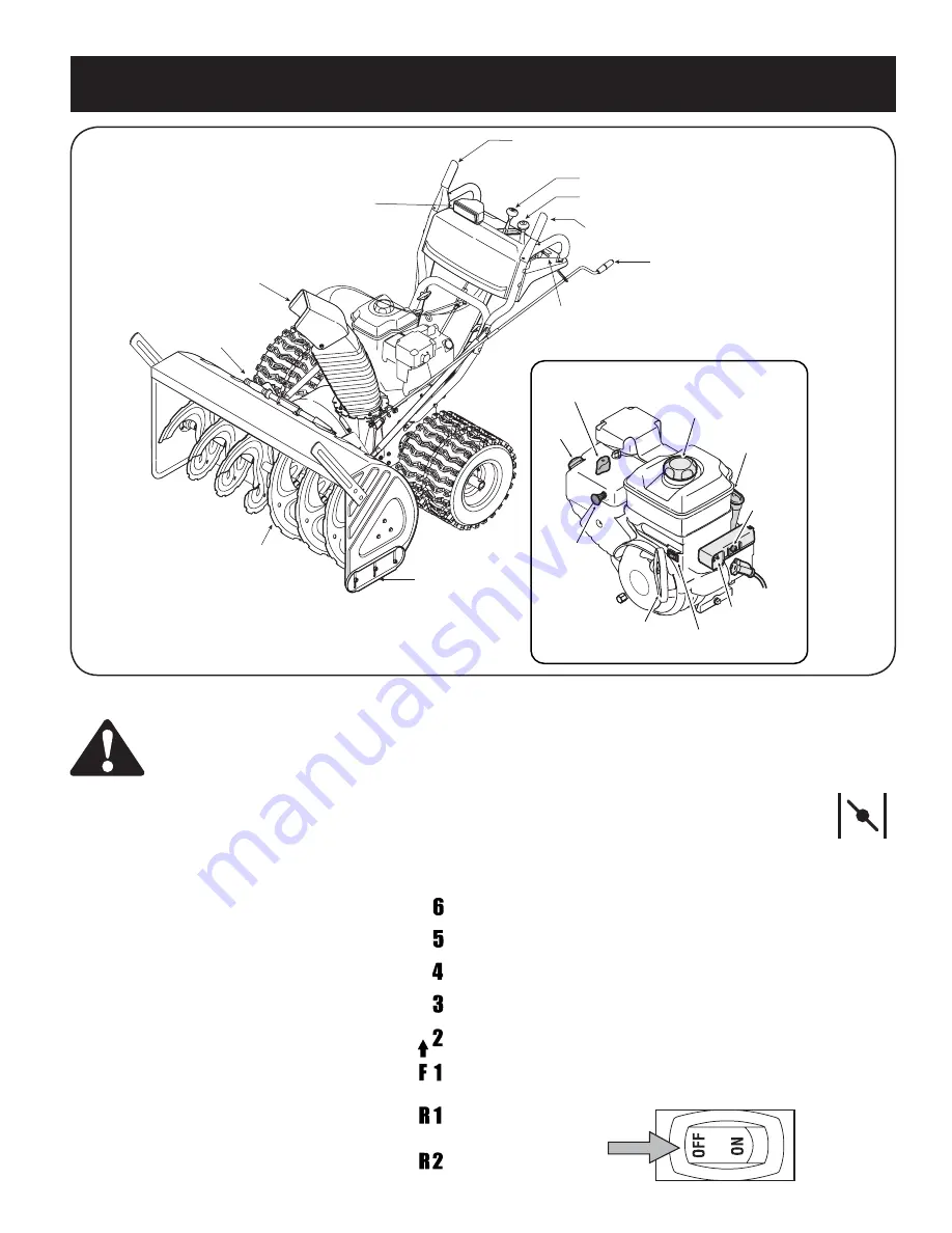
Reverse: The snow thrower has two reverse (R) speeds—R1 is the 
slower of the two.

Choke Control

The choke control is found on the top of the engine and is 
activated by rotating the knob counter clockwise. Activating 
the choke control closes the choke plate on the carburetor 
and aids in starting the engine.

Primer

Depressing the primer forces fuel directly into the engine’s carburetor 
to aid in cold-weather starting.

Oil Fill

Engine oil level can be checked and oil added through the oil fill.

Safety Key

The safety key must be pushed in place in order for the engine to start. 
Pull the safety key out to prevent unauthorized use of equipment.

Rocker Switch

The rocker switch is used to stop the engine.  The switch must be in 
the “ON” position in order to start the engine.

Figure 12

WARNING: Read, understand, and follow all 
instructions and warnings on the machine and in 
this manual before operating.

Now that you have set up your snow thrower for operation, get 
acquainted with its controls and features. These are described below 
and illustrated on this page. This knowledge will allow you to use your 
new equipment to its fullest potential. 

NOTE:  For detailed starting instructions and more 
information on all engine controls, refer to the separate 
engine manual packed with your unit.

Shift Lever

The shift lever is located in the center of the handle 
panel and is used to determine ground speed and 
direction of travel. It can be moved into any of eight 
positions. 

IMPORTANT: Always release drive control before 
changing speeds. 

Forward: The snow thrower has six forward (F) 
speeds. Position one (1) is the slowest and position six 
(6) is the fastest.

Engine Controls

Recoil Starter 

Handle

Choke

Control

Electric Starter

Outlet

(optional)

Electric Start

Button

(optional)

Primer

Safety

Key

Rocker 


Switch

Oil Fill

Gas Cap

Chute Assembly

Clean-Out Tool

Drive Control

Two-Way Chute Control

Auger Control

Wheel Steering 

Control

Skid Shoe

Chute

Directional

Control

Shift Lever

Headlight

Augers

Summary of Contents for C459-52926

Page 1: ...ollow all safety rules and operating instructions Operator s Manual SAFETY ASSEMBLY OPERATION MAINTENANCE PARTS LIST Sears Canada Inc 290 Yonge Street Toronto On M5B 2C3 Visit our web sears ca 6 8 2009 769 04182A 45 Large Frame Steerable Model No C459 52926 ...

Page 2: ...2 199260 07 21 05 BY Printed in U S A 02488 ...

Page 3: ...worn during normal use such as belts spark plugs air cleaners and shear pins as well damage to the 2 engine resulting from operating snow thrower with insufficient oil Repairs necessary because of operator abuse or negligence including the failure to operate and maintain 3 the equipment according to the instructions contained in the Owner s Manual 4 Tire replacement or repair caused by punctures f...

Page 4: ...ettes cigars pipes and other sources of ignition c Never fuel machine indoors d Never remove gas cap or add fuel while the engine is hot or running e Allow engine to cool at least two minutes before refueling f Never over fill fuel tank Fill tank to no more than inch below bottom of filler neck to provide space for fuel expansion g Replace gasoline cap and tighten securely h If gasoline is spilled...

Page 5: ...ol levers and stop the engine Wait until the auger impeller come to a complete stop Disconnect the spark plug wire and ground against the engine to prevent unintended starting 3 Check bolts and screws for proper tightness at frequent intervals to keep the machine in safe working condition Also visually inspect machine for any damage 4 Do not change the engine governor setting or over speed the eng...

Page 6: ... impeller housing or chute assembly Contact with the rotating parts can amputate hands and feet WARNING THROWN OBJECTS This machine may pick up and throw and objects which can cause serious personal injury WARNING GASOLINE IS FLAMMABLE Allow the engine to cool at least two minutes before refueling WARNING CARBON MONOXIDE Never run an engine indoors or in a poorly ventilated area Engine exhaust con...

Page 7: ...side of machine are observed from the operating position Assembling Handle Look at the lower rear of the snow thrower frame to be sure the spring found at the end of each cable is attached to its actuator bracket Remove the lower handle knobs washers and carriage bolts from each side of the upper handle See Figure 2 Raise the upper handle assembly until it locks over the lower handle See Figure 1 ...

Page 8: ... rod Tap the connector until the lower rod is completely through the connector See Figure 6 NOTE If the connector is not properly assembled the shift rod will pivot and you will not be able to change speeds or direction NOTE If the full range of speeds forward and reverse cannot be achieved refer to the Adjustment Section Normally the cable ties holding the steering cables against the handle are l...

Page 9: ...rd packed snow Adjust downward when operating on gravel or crushed rock surfaces See Making Adjustment Section Tire Pressure Pneumatic Tires The tires are over inflated for shipping purposes Check the tire pressure before operating the snow thrower Refer to the tire side wall for tire manufacturer s recommended psi and deflate or inflate the tires as necessary IMPORTANT If the tire pressure is not...

Page 10: ...gine as instruct ed on page 12 Make sure the throttle is set in the fast position While standing in the operator s position behind the snow thrower engage the auger Allow the auger to remain engaged for approximately ten seconds before releasing the auger control Repeat this several times With the engine running in the fast position and the auger control lever in the disengaged up position walk to...

Page 11: ... before operating Now that you have set up your snow thrower for operation get acquainted with its controls and features These are described below and illustrated on this page This knowledge will allow you to use your new equipment to its fullest potential NOTE For detailed starting instructions and more information on all engine controls refer to the separate engine manual packed with your unit S...

Page 12: ...rank clockwise to discharge to the left Crank counterclockwise to discharge to the right Wheel Steering Controls The left and right wheel steering controls are located on the underside of the handles Squeeze the right control to turn right squeeze the left control to turn left NOTE Operate the snow thrower in open areas until you are familiar with these controls Chute Clean Out Tool WARNING Never ...

Page 13: ...s to avoid the possibility of electric shock Follow all instructions carefully prior to operating the electric starter If you have a grounded three prong receptacle proceed as follows 1 Plug the extension cord into the outlet located on the engine s surface Plug the other end of extension cord into a three prong 120 volt grounded AC outlet in a well ventilated area 2 Push starter button to start e...

Page 14: ...up for a few minutes The engine will not develop full power until it reaches operating temperature WARNING The temperature of the muffler and the surrounding areas may exceed 150 F 65 C Avoid these areas 1 If possible remove snow immediately after it falls 2 Discharge snow downwind whenever possible 3 Slightly overlap each previous path 4 Set the skid shoes 1 4 below the shave plate for normal usa...

Page 15: ...r removed See Figure 14 5 From the direction noted earlier insert the ferrule into the proper hole 6 Reinstall the washer and the internal cotter pin Drive Control WARNING Run the engine completely dry of gasoline before tipping snowthrower Refer to the Final Adjustment section of the Set Up instructions to adjust the drive control To further check the adjustment proceed as follows 1 Tip the snow ...

Page 16: ... not remove the hex flange locknuts which fasten the skid shoe to the auger housing 2 Raise or lower the skid shoe to desired position 3 Retighten the hex nuts loosened earlier NOTE Make certain the bottom surface of skid shoe is flat against the ground to avoid uneven wear 4 Repeat on the other side of the snow thrower Auger Control Refer to instructions on page 9 to adjust the auger control Make...

Page 17: ... of the snow thrower are subject to wear They should be checked periodically and replaced when necessary To remove skid shoes 1 Remove the carriage bolts and washers if equipped and hex flange nuts which secure the skid shoes to the snow thrower 2 Reassemble new skid shoes with previously removed hardware Refer to Figure 21 To remove shave plate 1 Remove the carriage bolts and hex nuts which attac...

Page 18: ...crews securing the frame to the auger housing assembly See Figure 27 NOTE Do not remove the lower hex flange lock nut on each side 8 Place a block of wood underneath the auger housing as shown in Figure 28 and separate auger housing from the frame by tilting the housing forward and pulling up the handles 9 Block the impeller with a piece of wood to prevent if from spinning and use a 1 2 wrench to ...

Page 19: ... screw 14 Insert the hex screw through the pulley assembly and into the threads of the input shaft Torque the hex screw to 250 325 in lbs to secure the auger pulley assembly on the input shaft If also replacing the drive belt proceed to the Drive Belt instruction If not reassemble by performing the previous steps in the opposite order and manner of removal NOTE Make sure to remove the piece of woo...

Page 20: ...fall and the sprocket should remain hanging lose in the chain 6 Lift the friction wheel assembly out between the axle shaft and the drive shaft assemblies 7 Remove four screws securing the friction wheel rubber between the friction wheel plates See Figure 32 Discard old rubber 8 Reassemble the new friction wheel rubber to the friction wheel assembly tightening the four screws in rotation and with ...

Page 21: ...epare for storage as instructed in the separate engine manual packed with your snow thrower Clean snow thrower thoroughly Lubricate as instructed in the Maintenance section of this manual Refer to engine manual for correct engine storage instructions Store the snow thrower in a clean dry area When storing any type of power equipment in a poorly ventilated or metal storage shed care should be taken...

Page 22: ...ap Be certain vent is clear 3 Contact Service Center 1 Spark plug wire loose 2 Gas cap vent plugged 3 Exhaust port plugged Unit fails to propel itself 1 Adjust drive control cable Refer to Adjustments 2 Replace drive belt 3 Replace friciton wheel 1 Drive control cable in need of adjust ment 2 Drive belt loose or damaged 3 Friction wheel worn Excessive Vibration 1 Loose parts or damaged auger 1 Sto...

Page 23: ...23 notes ...

Page 24: ...25 70 71 69 57 56 49 63 44 43 52 58 21 5 26 33 38 20 19 34 3 19 32 21 2 39 7 36 14 1 41 19 19 35 29 31 19 68 47 60 61 2 64 65 71 4 59 51 28 45 57 40 48 31 62 69 66 67 24 47 37 27 15 16 10 18 47 68 53 54 69 16 55 46 9 8 23 28 11 28 12 13 30 72 73 22 ...

Page 25: ...t Rod Tige de commande supérieur 37 784 5680 RH Handle Support Brkt 5 8 Support de guidon droit 5 8 po 38 749 0989A Upper Handle LH Guidon supérieur CG 39 749 0990A Upper Handle RH Guidon supérieur CD 40 749 0991 Lower Handle Guidon supérieur 41 750 0963 Connector Shift Rod Raccord tige de changement de la vitesse 42 684 0102A Handle Panel Support Ass y Ensemble de suppport de panneau 43 710 0276 ...

Page 26: ... 4 43 43 24 71 24 18 66 3 63 40 38 69 48 31 10 63 6 64 17 62 7 37 39 33 65 16 57 30 45 55 47 76 61 75 34 34 5 68 17 Torque to 325 450 in lbs Serrez à un couple de 325 450 po lb Torque to 325 550 in lbs Serrez à un couple de 325 550 po lb 29 B B S B S B S 94 29 79 81 12 14 90 49 100 28 79 89 44 78 99 83 88 85 77 93 87 15 84 22 97 46 98 95 91 87 92 80 86 102 101 103 ...

Page 27: ...12 0413 Hex Jam Locknut 5 8 18 Gr 5 Nylon Contre écrou de blocage 5 8 18 Qual 5 31 710 04484 TT Screw 5 16 18 x 75 Vis taraudée 5 16 18 x 0 75 32 712 0717 Nut Insert 3 8 16 UNC Écrou inserer 3 8 16 UNC 33 713 0284 41 Chain 1 2 pitch x 36 links Endless Chaîne no 41 pas de 1 2 po x 36 maillons 34 713 0286 420 Chain 1 2 pitch x 40 links Endless Chaîne no 420 pas de 1 2 po x 40 maillons 35 713 04015 1...

Page 28: ...0 83 710 1245B Hex Hd Cap Scr 5 16 24 x 0 75 Gr 5 Boulon hex 5 16 24 x 0 75 Qual 5 84 714 0118 Square Key 1 4 x 1 4 x 1 50 Lg Clavette 1 4 x 1 4 x 1 50 po de lg 85 790 00167A Belt Keeper Bracket Support du protecteur de la courroie 86 731 2531 Belt Cover Courvercle de la courroie 87 732 04308A Torsion Spring 850 x 3 33 Lg Ressort de torsion 0 850 x 3 33 po de lg 88 748 0234 Shoulder Spacer 25 THK ...

Page 29: ...ocknut 5 16 18 Gr F Nylon Contre écrou à embase 5 16 fil 18 Qual F 4 710 1003 Hex Tapp Wash Hd Scr 10 x 5 8 Vis n 10 x 5 8 5 625 04053 Top Mounting Halogen Lamp Assembly Phare à iode 6 710 1240 Phillips Pan Hd Scr M4 x 16mm Vis Phillips à tête cylindrique M4 x 16mm 7 731 1364 Halogen Lamp Housing Boîtier du phare à iode 8 725 1669 Lamp Lens Housing Ass y Boîtier du phare optique 9 705 5217 Lamp Mo...

Page 30: ...uld ride slightly above asphalt Set to maximum for gravel driveways La plaque de râclage doit être légèrement au dessus du goudron Réglez la au maximum en cas d allées gravillonnées When rebuilding gear box fill one housing half completely with grease 838 0168 Pour remonter la boîte d engrenages remplissez complètement une moitié avec de la graisse no 838 0168 Torque to 20 30 in lbs Serrez à un co...

Page 31: ...ulement dia 0 625 x 0 170 po 36 784 0385C Auger Idler Bracket Support de tension de la tarière 37 736 0174 Wave Washer 625 ID x 885 OD x 015 Rondelle ondulée 0 625 DI x 0 885 DE x 0 015 38 710 0451 Carriage Bolt 5 16 18 x 75 Boulon ordinaire 5 16 18 x 0 75 39 710 04606A Screw 5 16 18 x 43 Vis 5 16 18 x 0 43 40 747 0980A Auger Idler Rod Tige de tension de la tarière 41 756 0178 Flat Idler Pulley Po...

Page 32: ...04067A Pulley Adapter 75 Dia w pins Adaptateur de poulie 0 75 diam avec attaches 84 710 0376 Hex Hd Cap Scr 5 16 18 x 1 0 Gr 5 Vis à tête hex 5 15 18 x 1 0 Qual 5 85 710 0262 Carriage Bolt 5 16 18 x 1 00 Lg Boulon ordiinaire de 5 16 18 x 1 00 po de lg 8012_599 6 8 09 AUGER HOUSING COMPONENTS COMPOSANTS DU LOGEMENT DES TARIÈRES SIZE TAILLE DESCRIPTION AUGER HOUSING LOGEMENT DES TARIÈRES LH AUGERS T...

Page 33: ...NOTES 33 ...

Page 34: ...NOTES 23 ...

Page 35: ... est mal réglé Moteur surchauffe Perte de puissance 1 Branchez et serrez le fil de la bougie 2 Dégagez la glace et la neige du chapeau Assurez vous de la propreté du trou d aération 3 Adressez vous à une station technique 1 Fil de la bougie desserré 2 Chapeau d échappement du trou d aération bouché 3 Le port déchappement est bouché La souffleuse n avance pas 1 Réglez le câble d entraînement Voir l...

Page 36: ...NT N entreposez jamais le mo teur avec du carburant dans le réservoir à l intérieur ou dans des endroits fermés si la ventilation n est pas adéquate et si les vapeurs de carburant peuvent venir en contact avec une flamme ou une étincelle ou veilleuse d un chauffe eau un radiateur un fourneau un sêche linge ou autre appareil à gaz Si le moteur doit être entreposé pendant plus de 30 jours préparez l...

Page 37: ...deuses du couvercle du châssis sous la souffleuse Voir la Figure 15 3 Enlevez la roue droite et dégagez celle ci de l essieu 4 Utilisez une clé de 3 4 po pour maintenir l arbre hexagonal puis retirez la vis à tête hex et la rondelle creuse du côté gauche du châssis Voir la Figure 31 5 Tenez la roue de frottement et dégagez l arbre hexagonal de la machine en le glissant vers le côté droite La ronde...

Page 38: ...ez la poulie de la tarière à fond sur l adaptateur tout en alignant les fentes de la poulie et les taquets de l adaptateur Voir la Figure 29 REMARQUE Si l adaptateur de la poulie a été démonté en même temps que la poulie alignez les cannelures de l adaptateur de la poulie et l arbre d admission de la tarière et poussez la poulie et l adaptateur sur l arbre d admission Voir la Figure 29 13 Glissez ...

Page 39: ...roie et le support de la poulie motrice Voir la Figure 24 Courroie d entraînement de la tarière 4 Retirez la goupille fendue et la rondelle plate de la virole pour dégager la tige de tension de la tarière du support du frein comme à la Figure 25 REMARQUE Assurez vous de ne pas déplacer la virole sur la tige de tension de la tarière 5 Dégagez la courroie d entraînement de la tarière courroie avant ...

Page 40: ...ison Vaporisez un lubrifiant à l intérieur de l arbre et autour des entretoises Lubrifiez aussi les roulements à bride trouvés à chaque extrémité de l arbre de la tarière Voir la Figure 20 Lame et patins La lame plate et les patins sont installés sous la souffleuse et ils ris quent de s user Vérifiez les régulièrement et remplacez les au besoin Pour démonter les patins 1 Enlevez les boulons ordina...

Page 41: ...s ne les retirez pas 2 Relevez ou abaissez le patin à la position voulue 3 Serrez les écrous à six pans desserrés plus tôt REMARQUE Vérifiez que toute la surface inférieure des patins est de niveau et en contact avec le sol pour éviter leur usure inégale 4 Répétez l ajustement sur l autre patin Commande de la tarière Consultez les instructions à la page 9 pour ajuster la commande de la tarière Vér...

Page 42: ...ne Commande de l entraînement des roues AVERTISSEMENT Laissez tourner le moteur jusqu à ce qu il tombe en panne d essence avant de faire basculer la souffleuse Consultez la partie concernant le Réglage final dans le chapitre Instructions de Montage pour régler la commande d entraînement Pour vérifier ce réglage procédez comme suit 1 Videz l essence qui se trouve dans le moteur de la souffleuse et ...

Page 43: ...ner pendant quelques minutes car il ne développe toute sa puissance que lorsqu il atteint sa tempéra ture de fonctionnement normale AVERTISSEMENT La température du silencieux et des zones voisines peut dépasser 150 F 65 C Évitez de les toucher 1 Le déblaiement sera plus facile s il est effectué peu de temps après une chute de neige 2 Dans la mesure du possible projetez la neige dans le sens du ven...

Page 44: ...st équipé d un fil et d une prise électrique à trois fils et il est conçu pour fonctionner sur un courant de 120 volts C A Il doit toujours être relié à la terre pour éviter la possibilité d une décharge électrique qui pourrait blesser le conducteur Suivez soigneuse ment toutes les instructions avant d utiliser le démarreur électrique Si vous avez une prise de courant à trois trous relié à la terr...

Page 45: ... dans le sens des aiguilles d une montre pour décharger la neige à gauche Tournez la manivelle en sens inverse pour décharger la neige à droite Commande d orientation des roues Les commandes d orientation des roues de droite et de gauche se trouvent en dessous des poignées Serrez la commande de droite pour tourner vers la droite ou serrez celle de gauche pour tourner vers la gauche REMARQUE Utilis...

Page 46: ...s et diverses caractéristiques expliquées ci dessous et représentées sur ce page Vous pourrez ainsi bénéficier au maximum de votre nouvelle machine REMARQUE Consultez la notice d utilisation du moteur emballée séparément avec votre souffleuse pour avoir plus de renseignements concernant le démarrage et les commandes du moteur Levier de vitesses Il se trouve au milieu du tableau de bord et sert à c...

Page 47: ... aéré et faites démarrer la souffleuse selon les instructions de la page 12 Vérifiez que l obturateur est réglé à la position rapide Tenez vous à la position de conduite derrière la souffleuse et enclenchez la tarière Attendez environ dix secondes avant de débrayer la tarière Répétez cette opération plusieurs fois Laissez tourner le moteur à plein régime et gardez la commande de la tarière à la po...

Page 48: ...ez les si la neige est tassée et abaissez les pour travailler sur des surfaces recouvertes de gravier ou de pierre concassée Consultez le chapitre Réglages Pression des pneus Bandages pneumatiques Les pneus sont gonflés excessivement pour l expédition Avant l utilisation vérifiez la pression des pneus avant d utiliser la souffleuse La pression recommandée par le fabricant est indiquée sur le flanc...

Page 49: ... abaissez le raccord des tiges sur l extrémité de la tige du levier de vitesses inférieure Tapez sur le raccord jusqu à ce qu il passe bien à travers la tige du levier de vitesses inférieure Voir la Figure 6 REMARQUE Si le raccord n est pas bien installé la tige du levier de vitesses pivotera et il sera impossible de changer de vitesse ou de direction REMARQUE S il n est pas possible d utiliser to...

Page 50: ... derrière la souffleuse Montage du guidon Vérifiez que tous les câbles sont alignés avec les galets de guidage sur l arrière du châssis de la souffleuse avant de redresser le guidon Assurez vous que le ressort qui se trouve à l extrémité de chaque câble est attaché à son support Enlevez les boutons et les boulons ordinaires inférieurs de chaque côté du guidon supérieur Voir la Figure 2 Relevez le ...

Page 51: ... pièces en mouvement de l habitacle des tarières de la turbine ou de la goulotte Les pièces en mouvement peuvent amputer mains et pieds AVERTISSEMENT OBJETS PROJETÉS Cette machine peut ramasser et projeter des objets ce qui peut causer des blessures graves AVERTISSEMENT L ESSENCE EST UN PRODUIT INFLAMMABLE Laissez le moteur refroidir pendant au moins deux minutes avant de refaire le plein AVERTISS...

Page 52: ...êtez le moteur Attendez que la tarière turbine se soit complètement immobilisée Débranchez le fil de la bougie et mettez le à la terre pour empêcher tout démarrage accidentel pendant le nettoyage la réparation ou l examen de la machine 3 Vérifiez régulièrement que les boulons et vis sont bien serrés et maintenez la machine en bon état de marche Examinez soigneusement la machine pour vous assurer q...

Page 53: ...ais le capuchon d essence et n ajoutez pas d essence pendant que le moteur tourne e Laissez le moteur refroidir pendant au moins deux minutes avant de faire le plein f Ne faites jamais déborder le réservoir Laissez un espace d un demi pouce environ pour permettre l expansion du carburant g Resserrez bien le capuchon d essence h En cas de débordement essuyez toute éclaboussure sur le moteur et la m...

Page 54: ...ure normale comme les courroies les bougies les filtres à air et les goupilles de cisaillement ainsi que tout dégât 2 au moteur résultant de l utilisation de la souffleuse avec une quantité d huile insuffisante Les réparations nécessaires en raison de l utilisation abusive ou négligente y compris l utilisation et l entretien de l équipement ne re 3 spectant pas les instructions fournies dans la no...

Page 55: ...s proche afin d apporter à l atelier des produits tels que des aspirateurs tondeuses à gazon ou appareils électroniques Pour connaître le no de téléphone du Service des pièces et de l entretien Sears afin de commander les pièces de rechange accessoires et manuels d instructions requis pour effectuer vous même les réparations www sears ca Pour acheter ou demander des renseignements sur un contrat d...

Page 56: ...a ATTENTION Lisez attentivement les régles de sécurité et les instructions avant de mettre en marche la machine Notice d utilisation SÉCURITÉ MONTAGE UTILISATION ENTRETIEN PIÈCES DÉTACHÉES Souffleuse à neige à grand châssis orientable de 45 po Modèle No C459 52926 6 8 2009 769 04182A ...

Reviews: