background image

11

E

Checking Laser Accuracy

The laser tools are sealed and calibrated at the factory. 
It is recommended that you perform an accuracy check


prior to using the laser for the first time 

(in case the 

laser was exposed to extreme temperatures) and then 
regularly to ensure the accuracy of your work.

 When 

performing any of the accuracy checks listed in this 

manual, follow these guidelines:

• Use the largest area/distance possible, closest to the 

operating distance. The greater the area/distance, the 
easier to measure the accuracy of the laser.

• Place the laser on a smooth, flat, stable surface that 

is level in both directions.

• Mark the center of the laser beam.

Horizontal Beam - Scan Direction

Checking the horizontal scan calibration of the laser 
requires two walls at least 30’ (9m) apart. It is important 
to conduct a calibration check using a distance no 
shorter than the distance of the applications for which 
the tool will be used.

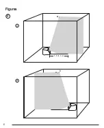
1.


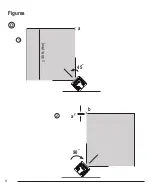
Place the back of the laser against a wall and facing 
straight ahead toward the opposing wall (Figure 

D


1

). 

2.


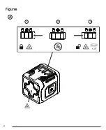
Move the Power/Transport Lock switch to the right 
(Figure 

A


3

) to turn the laser ON in self-leveling 

mode and display the horizontal and vertical beams. 

3.


Turn the laser 45º counter-clockwise so that the 
right-most end of the laser line is displayed on the 
wall.

4.


Mark 

a

 on the center of the beam on the wall.

5.


Turn the laser 90º clockwise so that the left-most 
end of the laser line is displayed near 

a

 (Figure 

D


2

).

6.


Mark 

b

 on the center of the beam on the wall.

7.


Measure the vertical distance between 

a

 and 

b

.

8.


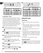
If your measurement is greater than the 

Allowable 

Distance Between 

a

 and 

b

 for the corresponding 

Distance Between Walls

 in the following table, the 

laser must be serviced at an authorized service 
center.

Distance 

Between Walls

Allowable Distance

Between 

a

 and 

b

30’ (9m)

15/32” (12mm)

40’ (12m)

9/16” (14.4mm)

50’ (15m)

23/32” (18mm)

Horizontal Beam - Pitch Direction

Checking the horizontal pitch calibration of the 
laser requires a single wall at least 30’ (9m) long. 
It is important to conduct a calibration check using 
a distance no shorter than the distance of the 
applications for which the tool will be used.

1.


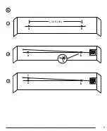
Place the laser against the end of the wall (Figure 

E


1

).

2.


Move the Power/Transport Lock switch to the right 
(Figure 

A


3

) to turn the laser ON in self-leveling 

mode and display the horizontal and vertical beams. 

3.


At least 30’ (9m) apart along the laser beam, mark 

a

 and 

b

.

4.


Move the laser to the opposite end of the wall  
(Figure 

E


2

).

5.


Position the laser toward the first end of the same 
wall and parallel to the adjacent wall.

6.


Adjust the height of the laser so the center of the 
beam is aligned with 

b

.

7.


Directly above or below 

a

, mark 

c

 along the laser 

beam (Figure 

E


3

).

8.


Measure the distance between 

a

 and 

c

.

Summary of Contents for CMHT77630

Page 1: ...CMHT77630 Self LevelingCross line Laser E ES F Please read these instructions before operating the product www CRAFTSMAN com ...

Page 2: ...A 1 2 4º _ 3 Figures 2 ...

Page 3: ...C B 1 4 20 3 ...

Page 4: ...D 1 2 Figures 4 45 90 a b 30 9m _ a ...

Page 5: ...1 2 3 5 E a b c b a b 30 9m _ a b ...

Page 6: ...1 2 Figures 6 F a 5 1 5 m a b ...

Page 7: ...7 1 4 20 360º 1 7 5 2 4 3 6 8 G ...

Page 8: ...injury NOTICE Indicates a practice not related to personal injury which if not avoided may result in property damage If you have any questions or comments about this or any CRAFTSMAN tool go to www CRAFTSMAN com WARNING Read and understand all instructions Failure to follow the warnings and instructions in this manual may result in serious personal injury SAVE THESE INSTRUCTIONS WARNING Laser Radi...

Page 9: ...result Turn the laser off when it is not in use Leaving the laser on increases the risk of staring into the laser beam Do not modify the laser in any way Modifying the tool may result in hazardous laser radiation exposure Do not operate the laser around children or allow children to operate the laser Serious eye injury may result Do not remove or deface warning labels If labels are removed the use...

Page 10: ... B 3 When the laser is not in use keep the Power Transport Lock switch in the center OFF position Figure A 2 to save battery power Turning the Laser On 1 Place the laser on a smooth flat level surface with the laser facing straight ahead toward the opposing wall 0º position 2 Turn the laser ON to display the horizontal and vertical laser beams Either Move the Power Transport Lock switch to the lef...

Page 11: ... displayed on the wall 4 Mark a on the center of the beam on the wall 5 Turn the laser 90º clockwise so that the left most end of the laser line is displayed near a Figure D 2 6 Mark b on the center of the beam on the wall 7 Measure the vertical distance between a and b 8 If your measurement is greater than the Allowable Distance Between a and b for the corresponding Distance Between Walls in the ...

Page 12: ...ceiling mark a This should be directly over the midpoint of the line on the floor 5 Move the laser to the other end of the line on the floor Figure F 2 6 Where the vertical laser beam appears on the ceiling mark b directly beside the first mark a 7 Measure the distance between a and b 8 If your measurement is greater than the Allowable Distance Between a and b for the corresponding Ceiling Height ...

Page 13: ...igure G 8 clockwise until the clamp is tight around the object and the bracket is held in place Using the Laser with Other Accessories WARNING Since accessories other than those offered by CRAFTSMAN have not been tested with this laser use of such accessories with this laser could be hazardous Only use CRAFTSMAN accessories that are recommended for use with this model Accessories that may be suita...

Page 14: ...much that the internal mechanism cannot level itself or the laser is not level when in manual mode the laser beams will flash indicating that the tilt range has been exceeded THE FLASHING BEAMS CREATED BY THE LASER ARE NOT LEVEL OR PLUMB AND SHOULD NOT BE USED FOR DETERMINING OR MARKING LEVEL OR PLUMB Try repositioning the laser on a more level surface The Laser Beams Will Not Stop Moving The lase...

Page 15: ...ser Wavelength 510 530 nm visible Laser Power 1 5 mW CLASS 2 LASER PRODUCT Working Range 53 16m Accuracy 3 16 30 4 5mm 9m Power Source 2 AA 1 5V size batteries 3V DC Operating Temperature 14 F to 104 F 10 C to 40 C Storage Temperature 5 F to 140 F 20 C to 60 C ...

Page 16: ...uación potencialmente peligrosa que si no se evita puede resultar en lesiones menores o moderadas AVISO Indica una práctica no relacionada con lesiones personales que si no se evita puede resultar en daño a la propiedad Si tiene cualquier pregunta o comentario sobre esta o cualquier herramienta CRAFTSMAN visite www CRAFTSMAN com ADVERTENCIA Lea y entienda todas las instrucciones La falla en seguir...

Page 17: ...r en lesiones serias a los ojos No coloque el láser en una posición que pueda causar que alguien observe intencional o inadvertidamente el rayo láser Podría resultar en lesiones serias a los ojos No coloque el láser cerca de una superficie reflejante que pueda reflejar el rayo láser a los ojos de alguien Podría resultar en lesiones serias a los ojos Apague el láser cuando no esté en uso Dejar el l...

Page 18: ...ser 2 En la parte inferior del láser levante el seguro para abrir la cubierta del compartimiento de baterías Figura B 1 3 Inserte dos baterías AA de marca de alta calidad nuevas asegurándose de colocar los extremos y de cada batería como se indica en el interior del compartimiento de baterías Figura B 2 4 Cierre la cubierta del compartimiento de baterías hasta que se conecte en su lugar Figura B 3...

Page 19: ...a herramienta 1 Coloque la parte trasera del láser contra una pared y viendo al frente hacia la pared opuesta Figura D 1 2 Mueva el interruptor de Bloqueo de energía Transporte a la derecha Figura A 3 para encender el láser en modo de nivelación automática y mostrar los rayos láser horizontal y vertical 3 Gire el láser 45º en sentido contrario a las manecillas del reloj de forma que el extremo der...

Page 20: ...erecha Figura A 3 para encender el láser en modo de nivelación automática y mostrar los rayos láser horizontal y vertical 3 Coloque el láser en un extremo de la línea sobre el suelo asegurándose que el rayo láser vertical esté alineado y centrado sobre la línea 4 Donde aparece el rayo láser vertical en el techo marque a Éste debe estar directamente sobre el punto medio de la línea sobre el piso 5 ...

Page 21: ...orte en su lugar 3 Use la abrazadera del soporte Figura G 6 para sostener el láser en su lugar sobre un perno rejilla de techo poste Si es necesario gire la abrazadera de forma que esté colocada en el ángulo correcto para conexión al objeto Mientras sostiene el brazo de soporte con una mano use su otra mano para girar la abrazadera Figura G 7 Coloque la abrazadera del soporte alrededor del perno r...

Page 22: ...que las baterías estén completamente cargadas Asegúrese de mantener el láser seco Si la unidad láser se calienta a más de 120 F 50 C la unidad no se encenderá Si el láser se ha almacenado a temperaturas extremadamente altas deje que se enfríe El nivel del láser no se dañará utilizando el interruptor de Bloqueo de encendido Transporte antes de enfriar a su temperatura de operación adecuada El rayo ...

Page 23: ...puede ocasionar lesiones Para localizar a su centro de servicio CRAFTSMANmás cercano visite www CRAFTSMAN com Especificaciones CMHT77630 Fuente de luz Diodos láser Longitud de onda de láser 510 530 nm visible Potencia de Láser 1 5 mW PRODUCTO LÁSER CLASE 2 Rango de Operación 53 16m Precisión 3 16 30 4 5mm 9m Fuente de energía 2 baterías tamaño AA 1 5V 3V CD Temperatura de operación 14 F a 104 F 10...

Page 24: ... potentiellement dangereuse qui si elle n est pas évitée peut entraîner une blessure légère ou modérée AVIS Indique une pratique non liée à une blessure corporelle qui si elle n est pas évitée peut entraîner des dommages matériels Si vous avez des questions ou des commentaires sur cet ou tout outil CRAFTSMAN visitez le www CRAFTSMAN com AVERTISSEMENT Lisez et comprenez toutes les instructions Ne p...

Page 25: ... pourrait faire en sorte que quelqu un fixe intentionnellement et non intentionnellement le faisceau du laser Cela pourrait entraîner une blessure oculaire grave Ne pas placer le laser près d une surface réfléchissante qui peut réfléchir le faisceau du laser vers les yeux d une personne Cela pourrait entraîner une blessure oculaire grave Éteignez le laser lorsque vous ne l utilisez pas Laisser le ...

Page 26: ...Tournez le laser à l envers 2 En bas du laser levez le loquet pour ouvrir le couvercle du compartiment à piles Figure B 1 3 Insérez deux nouvelles piles AAA de marque haute qualité en vous assurant de placer les extrémités et de chaque pile comme indiqué à l intérieur du compartiment à piles Figure B 2 4 Poussez le couvercle du compartiment à pile jusqu à ce qu il s enclenche en place Figure B 3 L...

Page 27: ... au mur opposé Figure D 1 2 Déplacez le bouton Alimentation Verrou de transport vers la droite Figure A 3 pour mettre en marche le laser en mode de nivellement automatique et montrer les faisceaux horizontal et vertical du laser 3 Tournez le laser à 45º dans le sens contraire des aiguilles d une montre afin que l extrémité la plus à droite de ligne du laser s affiche sur le mur 4 Indiquez a le cen...

Page 28: ...gure F 1 2 Déplacez le bouton Alimentation Verrou de transport vers la droite Figure A 3 pour mettre en marche le laser en mode de nivellement automatique et montrer les faisceaux horizontal et vertical du laser 3 Placez le laser à une extrémité de la ligne sur le plancher assurez vous que le faisceau du laser vertical est aligné et centré sur la ligne 4 À l endroit où le faisceau vertical apparaî...

Page 29: ...e G 5 Tournez le bouton d ajustement Figure G 3 dans le sens des aiguilles d une montre pour verrouiller le bras du support en place 3 Utilisez la pince du support Figure G 6 pour maintenir le laser en place sur un montant un serpentin plafonnier ou un poteau S il y a lieu tournez la pince afin qu elle se place dans le bon angle pour se fixer à l objet Tout en tenant le bras du support avec une ma...

Page 30: ...sont entièrement chargées Assurez vous de garder le laser sec Si l outil laser est chauffé au dessus de 50 C 120 F l outil s éteindra Si le laser a été entreposé dans des températures extrêmement chaudes laisser se refroidir Le niveau laser ne sera pas endommagé en utilisant le bouton Alimentation Verrou de transport avant de laisser refroidir à sa propre température de fonctionnement Les faisceau...

Page 31: ... Pour localiser le centre de services CRAFTSMANle plus près de chez vous consultez www CRAFTSMAN com Garantie Allez à www CRAFTSMAN com pour obtenir des informations sur la garantie Caractéristiques CMHT77630 Source de lumière Diodes lasers Longueur d onde du laser 510à530 nm visible Alimentation du laser PRODUIT LASER DE CLASSE 2 1 5 mW Plage de fonctionnement 53 pi 16 m Précision 3 16 po 30 4 5m...

Page 32: ... 2019 CRAFTSMAN 701 East Joppa Road Towson MD 21286 N599505 January 2019 www CRAFTSMAN com ...

Reviews: