background image

English

14

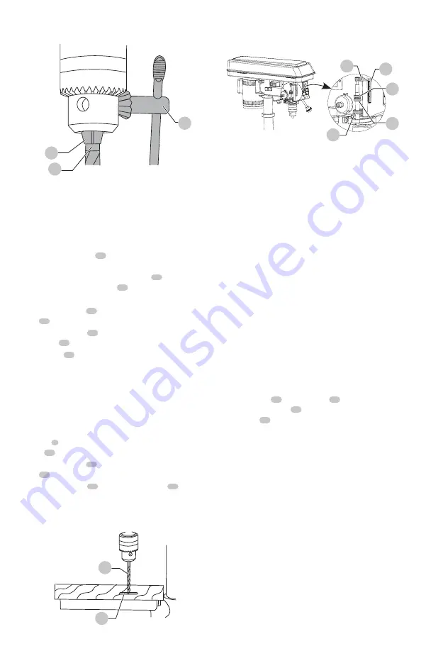
Drilling To a Specific Depth

Drilling a blind hole (not all the way through workpiece) to 
a given depth can be done two ways:

Workpiece Method (Fig. Y, Z)

1.  Make the depth mark 

 55 

 of the hole on the side of the 

workpiece.

2.  With the switch “OFF”, bring the drill bit 

 54 

 down until 

the tip is even with the mark 

 55 

.

3.  Hold the feed handle at this position.
4.  Spin the lower nut 

 56 

 down to contact the depth stop 

lug 

 57 

.

5.  Spin the upper nut 

 58 

 down and tighten against the 

lower nut 

 56 

.

6.  The drill bit 

 54 

 now will stop after traveling the 

distance marked on the workpiece.

Depth Scale Method (Fig. Z)

nOTE:

 With the chuck in the upper position, the tip of 

the drill bit must be just slightly above the top of the 
workpiece.

1.  With the switch “OFF”, turn the feed handle until the 

pointer 

 1 

 points to the desired depth on the depth 

scale 

 59 

 and hold the feed handle in that position.

2.  Spin the lower nut 

 56 

 down to contact the depth stop 

lug 

 57 

3.  Spin the upper nut 

 58 

 against the lower nut 

 56 

 and 

tighten.

4.  The drill bit will stop after traveling the distance selected 

on the depth scale.

Fig. X

53

54

37

Drill a Hole

Using a centre punch or a sharp nail, make an indentation 
in the workpiece where you want to drill. Turn the power 
switch on and pull down on the feed handles with only 
enough effort to allow the drill to cut.

FEEDING TOO RAPIDLY might cause the belt or drill to slip, 
tear the workpiece loose, or break the drill bit. When drilling 
metal, it will be necessary to lubricate the tip of the drill bit 
with metal drilling oil to prevent it from overheating.

Basic Operation Instructions

To get the best results and minimize the likelihood of 
personal injury, follow these instructions for operating your 
drill press.


WARNING:

 For your own safety, always observe the 

SAFETY INSTRUCTIONS

 listed on pages 4 and 5 of 

this instruction manual when operating the drill press.

Positioning The Table And Workpiece  

(Fig. AA, BB)

1.  Lock the table 

 20 

 to the column 

 19 

 at a position so 

the tip of the drill bit 

 54 

 is just above the top of the 

workpiece 

 60 

.

2.  ALWAYS place a BACK-UP MATERIAL (scrap wood) 

on the table beneath the workpiece. This will prevent 
splintering or heavy burring on the underside of the  
workpiece. To keep the back-up material from spinning, 
it MUST be positioned against the LEFT side of the 
column.


WARNING:

 To prevent the workpiece or backup 

material from being thrown while drilling, you 

MUST


position the workpiece against the 

LEFT

 side of the 

column. If the workpiece or the backup material is not 
long enough to reach the column, clamp them to the 
table, or use the fence provided with the drill press to 
brace the workpiece. Failure to secure the workpiece 
could result in personal injury.

3.  For a small piece that cannot be clamped to the table, 

use a drill press vise (optional accessory).


WARNING:

 When using a drill press vise, it 

MUST

 be 

clamped or bolted to the table to avoid injury from a 
spinning workpiece, or damaged vise or bit parts.

Fig. Z

Fig. Y

55

54

59

1

58

56

57

Summary of Contents for CMXEDAR300

Page 1: ... mm Drill Press 10 254 mm Perforadora de columna CMXEDAR300 INSTRUCTIONMANUAL MANUALDEINSTRUCTIONES IFYOUHAVEQUESTIONSORCOMMENTS CONTACTUS SITIENEDUDASOCOMENTARIOS CONTÁCTENOS 1 888 331 4569 WWW CRAFTSMAN COM ...

Page 2: ...English original instructions 1 Español traducido de las instrucciones originales 21 ...

Page 3: ... uses the following safety alert symbols and words to alert you to hazardous situations and your risk of personal injury or property damage DANGER Indicates an imminently hazardous situation which if not avoided will result in death or serious injury WARNING Indicates a potentially hazardous situation which if not avoided could result in death or serious injury CAUTION Indicates a potentially haza...

Page 4: ...ile operating power tools may result in serious personal injury b Use personal protective equipment Always wear eye protection Protective equipment such as dust mask non skid safety shoes hard hat or hearing protection used for appropriate conditions will reduce personal injuries c Prevent unintentional starting Ensure the switch is in the off position before connecting to power source and or batt...

Page 5: ...miliar noise or if it vibrates excessively stop immediately turn the drill press off and unplug Do not restart the unit until the problem is corrected DO NOT perform layout assembly or set up work on the table while the drill press is in operation USE THE RECOMMENDED SPEED for any drill press accessory and for different workpiece material READ THE INSTRUCTIONS that come with the accessory WHEN DRI...

Page 6: ...S AND SAFETY Power Supply And Motor Specification WARNING To avoid electrical hazards fire hazards or damage to the tool use proper circuit protection Use a separate electrical circuit for your tool Your grinder is wired at the factory for 120 V operation Connect to a 120 V 3 2 Amp circuit and use a 3 2 Amp time delay fuse or circuit breaker To avoid shock or fire if power cord is worn cut or dama...

Page 7: ...res W watts or AC alternating current or AC DC alternating or direct current Class II Construction double insulated no no load speed n rated speed earthing terminal safety alert symbol visible radiation avoid staring at light wear respiratory protection wear eye protection wear hearing protection read all documentation SAVE THESE INSTRUCTIONS FOR FUTURE USE Motor Be sure your power supply agrees w...

Page 8: ... the list below and the illustration below Place the drill press on a secure surface and examine it carefully WARNING To avoid injury from unexpected starting or electrical shock do not plug the power cord into a source of power during unpacking and assembly The cord must remain unplugged whenever you are adjusting assembling the drill press WARNING The drill press is heavy and should be lifted wi...

Page 9: ...r safety never connect plug to power source receptable until all assembly and adjustment steps are all complete and you have read and understood the safety instructions WARNING The drill press is a heavy power tool and should be lifted with the help of two people OR MORE to safely assemble it Assembling Column To Base Fig D 1 Remove the rack and rack ring from the column assembly 2 Position the ba...

Page 10: ...grease used in the packing of these parts must be removed otherwise the chuck may come loose during operation 1 Bag E Clean out the tapered hole in the chuck 21 with a clean cloth and a non alcohol based cleaner Wipe clean all oil reside and any dirt or grime thoroughly Fig L 2 Clean tapered surfaces on the spindle 36 in the same manner as above NOTE Make sure there are no foreign particles sticki...

Page 11: ...ctory Due to normal wear and use some occasional readjustments may be necessary WARNING To avoid injury from an accidental start ALWAYS make sure the switch is in the OFF position the switch key is removed and the plug is not connected to the power source outlet before making adjustments Bevel Drilling Fig P WARNING To prevent personal injury always disconnect the plug from the power source when m...

Page 12: ...RTIGHTEN and restrict quill movement 43 46 45 44 48 47 Fig R Fig Q 41 Belt Tension Fig S WARNING To avoid injury from an accidental start ALWAYS make sure the switch is in the OFF position the switch key is removed and the plug is not connected to the power source outlet before making belt adjustments 1 Open the pulley cover 2 To unlock the belt tension turn the belt tension lock knob 12 on the ri...

Page 13: ...Iron Steel 1 16 2800 2800 2800 1 8 2080 3 16 1500 1 4 2080 5 16 900 3 8 1500 1 2 2080 900 610 3 To lock the switch in the OFF position grasp the sides of the safety key and pull it out 4 With the safety key removed the switch will not turn the power tool on 5 If the safety key is removed while the drill press is running it can be turned OFF but cannot be restarted without inserting the safety key ...

Page 14: ...rkpiece loose or break the drill bit When drilling metal it will be necessary to lubricate the tip of the drill bit with metal drilling oil to prevent it from overheating Basic Operation Instructions To get the best results and minimize the likelihood of personal injury follow these instructions for operating your drill press WARNING For your own safety always observe the SAFETY INSTRUCTIONS liste...

Page 15: ...he table before operating the drill press 4 To return the table to its original position loosen the table bevel locking bolt 3 Return the table 20 to the 0 position 5 Return nut 39 on locking pin to the OUTSIDE END OF THREADS Gently tap locking pin until it is seated in the mating hole of the table bracket Hand tighten nut 39 Fig AA Fig BB 19 54 20 60 Fig CC 20 3 40 39 Feeding 1 Pull down the feed...

Page 16: ...arbon zinc or rechargeable nickel cadmium batteries Batteries are to be inserted with the correct polarity Do not charge the battery which is not a rechargeable battery WARNING To avoid shock or fire hazard if the power lead is worn or cut in any way replace it immediately LUBRICATION Ball bearings in the drill press are packed with grease at the factory and require no further lubrication Use only...

Page 17: ...eration Speeds and Belt Placement Table 2 Retract drill frequently to clear chips 3 Resharpen drill bit 4 Feed fast enough allow drill to cut 5 Lubricate drill Run out of drill bit point drilled hole not round 1 Grain in wood or lengths of cutting flutes and or angles not equal 2 Bent drill bit 1 Resharpen drill bit correctly 2 Replace drill bit Wood splinters on underside 1 No backup material und...

Page 18: ... 1 888 331 4569 This warranty does not apply to accessories or damage caused where repairs have been made or attempted by others THIS LIMITED WARRANTY IS GIVEN IN LIEU OF ALL OTHERS INCLUDING THE IMPLIED WARRANTY OF MERCHANTABILITY AND FITNESS FOR A PARTICULAR PURPOSE AND EXCLUDES ALL INCIDENTAL OR CONSEQUENTIAL DAMAGES Some states do not allow limitations on how long an implied warranty lasts or ...

Page 19: ...Y 1 X76K SWITCH PLATE 1 X83H DRIVE SLEEVE ASS Y 1 X76L SWITCH BOX 1 X83L TRADEMARK LABEL 1 X76M SCALE 1 X83M WARNING LABEL 1 X76P SET BOLT M10 1 5 1 X83N SPEED DIAGRAM 1 X76Q POINTER 1 X83P LABEL 1 X76R CR RE COUNT HD SCREW M4 10 2 X83R PHILIPS SCREW AND FLAT WASHER ASS Y M5 12 1 X76S CR RE COUNT HD SCREW S4 2 12 4 X83S CORD PLATE 1 X76X HEX NUT 3 8 24UNF T 8 2 X83U INSTRUCTION MANUAL 1 X770 CR RE...

Page 20: ...7792 X778 X77N2 X77B X77C X77D4 X77J2 X77E X76L X76K X76J X76S2 X77N2 X75A X76M X76H X769 X76B X76A X769 X768 X766 X7B1 X7B2 X75T X83Y X83D X841 X83C X83E X83S X76R2 X76S2 X839 X76Q X76P X75Q X83W X83B X75N3 X762 X7B7 X76X2 X75C X7B8 X77A2 X77N3 X77M3 X77L4 X847 X846 X77H X77L X7712 X7702 X772 X773 X774 D Hardware bag E Hardware bag X7B1 X766 X83F G Hardware bag X840 X761 X760 X841 X75N3 X762 ...

Reviews: