7
English
Minimum gauge for Extension Cords (AWg)
When using 120 volts only
Ampere Rating
Total length of Cord
More
Than
not
More
Than
25
7.62
50
15.24
100
30.48
150 ft.
45.72 m
AWG - American Wire Gauge
0
6
18
16
16
14
6
10
18
16
14
12
10
12
16
16
14
12
12
16
14
12
Not Recommended
WARNING:
This tool is for indoor use only. Do not
expose to rain or use in damp locations.
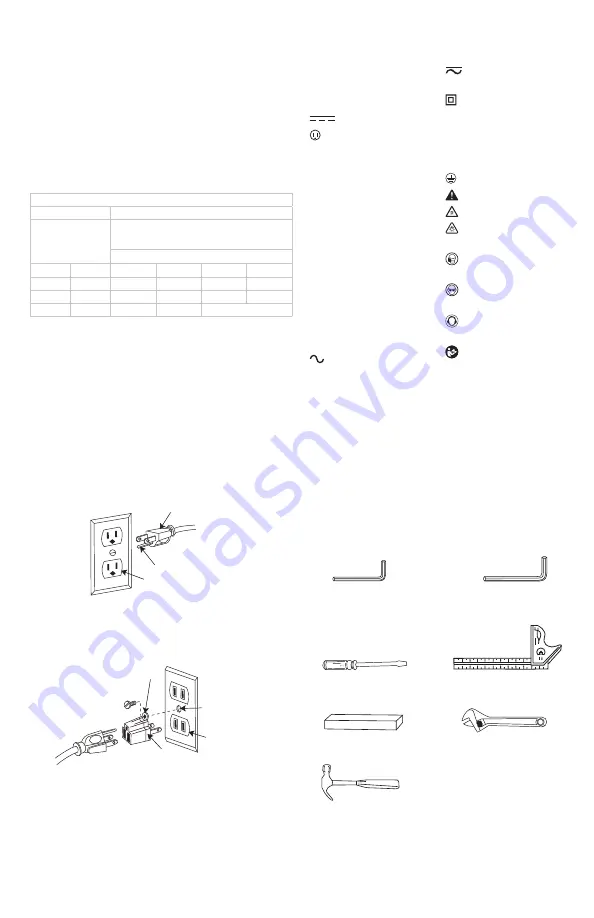
This tool is intended for use on a circuit that has a receptacle
like the one illustrated in Fig. B. Fig. B shows a three-pronged
electrical plug and receptacle that has a grounding conductor.
If a properly grounded receptacle is not available, an adapter
(Fig. C) can be used to temporarily connect this plug to a two-
contact grounded receptacle. The adapter (Fig. C) has a rigid
lug extending from it that MUST be connected to a permanent
earth ground, such as a properly grounded receptacle box.
The label on your tool may include the following symbols. The
symbols and their definitions are as follows:
V ......................... volts
Hz .......................hertz
min .....................minutes
or DC ......direct current
...................... Class I Construction
(grounded)
…/min ..............per minute
BPM ....................beats per minute
IPM .....................impacts per minute
RPM .................... revolutions per
minute
sfpm ................... surface feet per
minute
SPM ....................strokes per minute
OPM .................... oscillations per
minute
A .........................amperes
W ........................watts
or AC ...........alternating current
or AC/DC .... alternating or
direct current
...................... Class II
Construction
(double insulated)
no .......................no load speed
n .........................rated speed
......................earthing terminal
.....................safety alert symbol
.....................visible radiation
.....................
avoid staring at
light
..................... wear respiratory
protection
..................... wear eye
protection
..................... wear hearing
protection
..................... read all
documentation
SAVE THESE INSTRUCTIONS FOR
FUTURE USE
Motor
Be sure your power supply agrees with the nameplate
marking. Voltage decrease of more than 10% will cause loss
of power and overheating. These tools are factory tested; if
this tool does not operate, check power supply.
TOOLS NEEDED FOR ASSEMBLY
supplied
3 mm Hex key
4 mm Hex key
not supplied
Slotted Screwdriver
Back of Wood
Adjustable Wrench
Hammer or Rubber
Mallet
Combination Square
and burning out of the motor. The table below shows the
correct size to use depending on cord length and nameplate
ampere rating. If in doubt, use the next heavier gauge. The
smaller the gauge number, the heavier the cord.
Make sure your extension cord is properly wired and in good
condition. Always replace a damaged extension cord or have
it repaired by a qualified technician before using it. Protect
your extension cords from sharp objects, excessive heat and
damp or wet areas.
Fig. B
Fig. C
Three-Pronged Plug
Grounding Lug
Grounding Pronged Plug
Properly Grounding
Three-Pronged
Receptacle
Make sure this is
connected to a
known ground.
Two-Pronged
Receptacle
Adapter


