background image

Summary of Contents for CMXGBAM1054545

Page 1: ...rator sManualcovers severol models Feoturesmayvory bymodel Not011features Inthis monual are oppllcoble to 0 1 modelsand the modaldepictedmoydiffer from yours Thl tlrml Inawthrawlr and InawIIlawlr ma III ulld Intirehanglalll arthll praduet CRAFTBMANmIsareglstersd trodsmork01StanleyBlock Dscker lric ussdunderIIcsnse CRAFTBMANm ss unsmsrcorsglstrododeStonilYBlock Decksr InC utilizodobOjoIIclnclo 1Cl2...

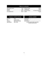
Page 2: ...SeeSeparate Supplement Service Maintenance Page 18 Espanol Page 28 PRODUCT SPECIFICATIONS Engine oil Fuel Spark Plug Spark Plug Gap 5W 30 Unleaded Gasoline F6RTC part 951 10292 020 to 0 030 MODEL NUMBER Model Number ____________ Serial Number _____________ Date of Purchase ____________ Record the model number serial number and date of purchase above 2 ...

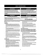
Page 3: ...earjewelry long scarves orother loose clothing which could become entangled in moving parts Wearfootwear which will improvefooting on slipperysurfaces 3 A DANGER This machinewas builttobe operated according to the safe operation practices in this manual Aswith any type ofpowerequipment carelessness orerroron the partofthe operatorcan result in serious injury This machine is capable ofamputatingfin...

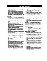
Page 4: ...any damage before starting and operating 4 Disengageall control leversand stop engine beforeyou leavetheoperating position behind the handles Wait until the auger impellercomesto acompletestop before unclogging the chuteassembly making any adjustments orinspections Never putyour hand in the dischargeorcollectoropenings Do not unclog chute assemblywhile engine is running Shutoffengineand remain beh...

Page 5: ...UsefulUfe ofseven 7 years or60 hours ofoperation Attheend of the Average UsefulUfe havethe machine inspected annually byan authorized service dealerto ensurethatall mechanical and safetysystems are working properlyand not worn excessively Failureto do so can resultin accidents injuriesordeath DO NOT MODIFY ENGINE Toavoidserious injuryordeath do not modify engine in anyway Tampering with thegoverno...

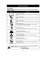
Page 6: ...parts in the auger impeller housing or chute assembly Contact with the rotating parts can amputate hands and f e e t WARNING THROWN OBJECTS This machine may pick up and throw and objects which can cause serious personal injury WARNING GASOLINE IS FLAMMABLE Allow the engine to cool at least two minutes before refueling WARNING CARBON MONOXIDE Never run an engine indoors or in a poorly ventilated ar...

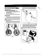
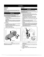
Page 7: ...nd remove the wrap around the handles NOTE Do notcutthecabletie sec ring the cablestQtheengine for units equipped NOTE Remove rubber bandssecuring cablesto carriage screws and cut cabletie securing shiftrod to lower lTandle 2 Observethe lowerreararea ofthesnow blowerto be sure both cablesare al1gned with rollerguides before pivoting the handle upward SeeFigure1 Figure 1 7 Figure 2 4 Place shiftlev...

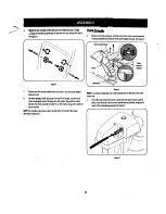
Page 8: ...nd pull thecabletieon theengine snug onthecablesto secure in place NOTE Forsmoothestoperation cablesshould all beto the leftofthechute directional control rod f Remove cotterpiil Wingnut and hexscrewfrom chute control head and clevispinandbow ti fOtterpin from chutesupportbracket See Figure5 8 figureS NOTE Forsmoothestoperation hecables should all beto the leftofthe chute control rod 2 Insertthe r...

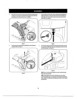
Page 9: ...7 FIgure 7 4 Finish securing chutecontrol head by installing hexscrewand wing nut removed in Step 2 See Figure 8 Figure 8 9 Figure 9 6 Push the chutecontrol rod toward the control panel until the hole inthe rod lines up with the middle hole in the chute control inputand insertthe cotter pin removed in Step 1 See Figure 10 Figure 10 NOTE There isareference hole provided at rearend ofcontrol rod to ...

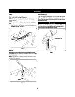
Page 10: ...7 in theOperation section for more Information regarding shearpin replacement NOll Iftheextra shear pins are not alreadyassembled in the handle panel they can befound inthe manual bag Figure12 ChuteClean OutTool Achute clean outtool isfastened to the top oftheauger housing with amounting clip See Figure 13 The tool isdesigned to clearachuteassembly oficeand snow This item isfastened With acabletie...

Page 11: ...iorto operating yoursnow blower carefully read and follow an instructions below Perform all adjustments to verify yoursnow blower is operating safely and properly Checkthe adjustmentofthe auger control as follows 1 Theauger control is located on the left handle See Figure 1 inset When the auger control is released and in the disengaged UP position the cable should have verylittle slack Itshould NO...

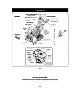
Page 12: ...trol 6 5 4 3 t 2 F1 I I __ Auger Housing Skid Shoe Oil Fill Electric Starter Button 81 82 Recoil Ilill t r p Handle Oil Drain Figure 16 Electric Starter Outlet SWitchbox MeetsANSI SafetyStandards Craftsman Snow Blowers conform to the safety standard ofthe American National Standards Institute ANSI 12 ...

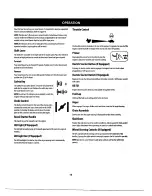
Page 13: ... handle is used to manually startthe engine LED light IfEquipped I O The LED light is located inside ofthe handle panel and is ON when the engine is running LED Ught Bar If Equipped The LED headlight is located on top oftheauger housing and is automatically turned ON when the engine is started Throttle Control 9 Thethrottle control is located o n the rearofthe engine It regulates the speedofthe en...

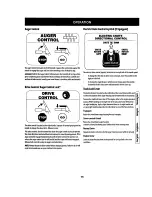
Page 14: ... s drivesystem ElectricChute ControlJoystick IfEquipped ELECTRIC CHUTE DIRECTIONAL CONTROL CHUTE ROTATE LEFT CHUTE ROTATE RIGHT The electric chute control joystick is located on the rightside ofthe handle panel To change the direction inwhich snowisthrown movethe joystickto the rightorto the left To changethe angle distancewhich snowisthrown pivotthejoystick forward to tiltthe chute down and backw...

Page 15: ... Tertiary Butyl Ether can be used Neverusean oil gasolinemixture ordirty gasoline Avoid getting dirt dust orwaterin thefueltank DO NOT use E85 gasoline Refuel in awell ventilated are withthe engine stopped Do notsmokeor allowflames orsparks in the area wherethe engineis refueled orwhere gasoline is stored Do notoverfill thefuel tank Afterrefueling make smethe tankcap is closed properlyand securely...

Page 16: ...ginestart Ifengine is warm place choke in RUN position 3 Push primerthree 3 times making sureto covervent hole when pushing Ifengine is warm push primeronlyonce Always covervent hole when pushing Cool weather may require priming to be repeated 4 Pull gently on the starter handle until it begins to resist th n pull quickly nd fO rcefullyto O vercO methecO mpressiO n DO nO t releasethe handleand all...

Page 17: ...ng instructions 2 Allowthe engineto warm upfor afew minutes astheenginewill not developfull poweruntil it reaches operating temperature 3 Rotate the chute assemblytothe desired direction awayfrom bystanders and or buildings 4 Making certain no bystandersorobstaclesare infrontofthe unit squeeze the augercontrol completelyagainstthe upper handletofully engagethe auger 5 Whiletheauger control is enga...

Page 18: ...lassification SG SF Motoroils classified SG SF will showthis designation on the container 1 Remove the oil filler cap dipstickand wipe the dipstickclean 2 Insertthe cap dipstick into the oilfiller neck butdo NOT screw it in 3 Remove the oil filler cap dipstick Iflevel is low slowly add oil until oil level registers between high H and low l See Figure 18 4 Replace and tighten cap dipstickfirmly bef...

Page 19: ...son or every25 hoursofoperation Change the spark plug once aseason orevery 100 hours To ensure proper engine operation the spark plug must be properlygapped and free ofdeposits 1 Removethe sparkplug bootand useasparkplug wrench to remove the plug See Figure 20 2 Visually inspectthe sparkplug Discard thespark plug ifthere isapparent wear orifthe insulator is cracked orchipped Clean the spark plug w...

Page 20: ...ure22 Chute Directional Control Onceaseason lubricate the eye boltbushing and spiral with 3 in l oil Auger Shaft At least onceaseason remove the shear pins on augershaft Spray lubricantinside shaft and around the spacers andflange bearingsfound at eitherend ofthe shaft See Figure 23 Figure23 Shave Plate and Skid Shoes Theshave plate and skid shoes on the bottom ofthesnow bloweraresubjectto wear Th...

Page 21: ... To ensure propershiftcabletension perform thefollowing a Startthe engine and placethe shiftleverintheslowestforward speed Using the drive control ensurethe unit movesforward b Placethe shiftleverintheslowest reversespeed Usingthedrive control ensurethe unit moves in reverse c Ifnecessarycontinuetoadjustcable until theconditions in Stepsaand bare satisfied ShiftRcid Iftheful rangeofspeeds forward ...

Page 22: ...ows a Shutoffthe engine asInstructed in the Operation section Chute Control Rod Toachieve morechutecontrol rod engagementinthe inputshaftunderthe handle panel the chute control rod will haveto be adj sted Refer to Figure 29 To adjustthis rod proceed asfollows 1 Remove thecotterpinfrom the hole closestto the chute control head on the chute control input 2 Pull oiltthe chute control rod until the ho...

Page 23: ...usting the skid shoes Continuous Tracks The snow bloweris equipped with an auto tensioneron both the leftand right sides Thesystem is designed to maintain constanttension on both tracks However ifthe snow blowerfails to propel itselfbecausethe track wheel is jumping drive lugs the tracks are too loose and are in need ofadjustment See an authorized Service Dealerto havethe tracks properlyadjusted S...

Page 24: ...blysection ofthis manual Drive Belt NOTE Several components must be removed and specialtools are required in order to replacethesnowblower sdrive belt Contactthe nearestParts RepairCenterto havethe drive beltreplaced Friction W eellnspection Ifunitfailsto drive with drivecontrol leverengaged and performing drivecontrol cableadjustmentfails to correct problem thefriction wheel may need to be repla ...

Page 25: ...foil on anyareasthatare susceptibleto rust Store In aclean dry and well ventilated area awayfrom anyappliancethat operateswith aflame or pilot light such as afurnace water heater or clothes dryer Avoid anyarea with aspark producing electric motor orwhere powertoolsare operated AWARNING Neverstoresnowblowerwith fuel in tankindoors orin poorlyventilated areas wherefuel fumes may reach an open flame ...

Page 26: ...electricstarter button on modelssoequipped outletand the otherendto athree prong 120V grounded AC outlet Engine runnihg erratically 1 Engine running on CHOKE 1 Movechokecontrolto RUN position inconsistentRPM hunting or 2 Stalefuel 2 Filltank with clean fresh gasoline surging 3 Waterordirtinfuel system 3 Drainfuel tank by runningengineuntil itstops Refill withfresh fuel 4 Carburetoroutofadjustment ...

Page 27: ...t RefertoServiceand Maintenancesection 5 Shearpints sheared 5 Replacewith newshearpints RefertoOperation section Chutefailsto easilyrotate 180 200 1 Chuteassembled incorrectly 1 Disassemblechutecontrol and reassembleasdirected iil the degrees Assemblysection Unitplowssnow insteadof 1 low slowgroundspeedinwet slushysnow 1 3 deep 1 Increase ground speed AlwaysoperateengineatFUllthrottle blowing it 2...

Reviews: