


EsPAÑOl
25
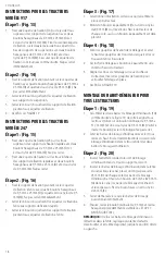
inStrUCCiOneS PArA trACtOreS De
mODeLO 917
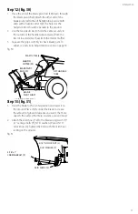
Paso 1: (fig. 13)
1. Instale un soporte angular (16) al conjunto superior
de orificios en los soportes colgantes con dos pernos
hexagonales de 3/8” x 1” (D) y tuercas mecánicas de
seguridad de 3/8” (M). Instale el segundo soporte
angular al segundo conjunto de orificios, desde abajo
hacia arriba, en los soportes colgantes con dos pernos
hexagonales de 3/8” x 1” (D) y tuercas mecánicas de
seguridad de 3/8” (M). Asegúrese de que los soportes
angulares estén girados como se muestra. No ajuste
todavía.
étape 2 : (fig. 14)
1. Instale el soporte pivotante en los soportes angulares
con cuatro pernos hexagonales de 3/8” x 1” (D) y
tuercas mecánicas de seguridad de 3/8” (M). No ajuste
todavía.
2. Ajuste los 4 pernos que sujetan los soportes angulares
a los soportes colgantes.
3. Ajuste los 4 pernos que sujetan el soporte pivotante a
los soportes angulares.
4. VAYA A LA FIGURA 19
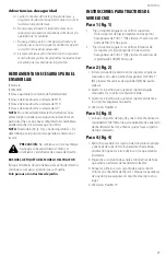
inStrUCCiOneS PArA trACtOreS De
mODeLO 247
Paso 1: (fig. 15)
1. Fije un soporte angular (23) a los orificios superiores
de los soportes de fijación rápida con dos pernos
hexagonales de 3/8” x 1” (D) y tuercas mecánicas de
seguridad de 3/8” (M). No ajuste.
2. Fije un soporte angular a los orificios inferiores en
los soportes de fijación rápida con dos pernos
hexagonales de 3/8” x 1” (D) y tuercas mecánicas de
seguridad de 3/8” (M). No ajuste.
Paso 2: (fig. 16)
1. Instale el soporte pivotante en los soportes angulares
ranurados con cuatro pernos hexagonales de 3/8” x 1”
(D) y tuercas mecánicas de seguridad de 3/8” (M). No
ajuste todavía.
2. Ajuste los 4 pernos que sujetan el soporte angular
ranurado a los soportes de fijación rápida.
3. Ajuste los 4 pernos que sujetan el soporte pivotante a
los soportes angulares ranurados.
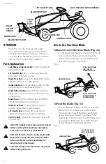
Paso 3: (fig. 17)
1. Seleccione la ilustración que se asemeje más a su
tractor.
2. Coloque un perno de tope (I) y una tuerca mecánica de
seguridad de 3/8” (M) en la parte delantera de cada
lado del bastidor del tractor, a menos que ya haya un
perno de tope instalado.
Paso 4: (fig. 18)
1. Retire los pasadores de sujeción del conjunto de acople
y gire la parte superior de los pasadores hacia abajo,
en dirección opuesta a los orificios en los que estaban
insertados.
2. Enganche el conjunto de acople en los pernos de tope
que están en el lateral del bastidor del tractor.
3. Alinee los orificios en el conjunto de acople con
los orificios en el bastidor del tractor. Coloque los
pasadores de sujeción para asegurar el conjunto de
acople en su lugar.
4. VAYA A LA FIGURA 19
enSAmbLAJe De PALA PArA tODOS LOS
trACtOreS
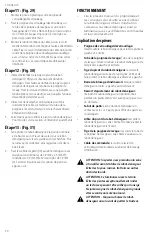
Paso 1: (fig. 19)
1. Instale las dos barras de bloqueo de ángulo (10) juntas,
como se muestra en la Figura 19, de forma que todos
los agujeros queden alineados. Use un perno con
cabeza de hongo de 3/8” x 1-1/4” (E) y una tuerca
mecánica de seguridad de 3/8” (M). Asegúrese de
insertar el perno desde el lado indicado. No ajuste.
2. Sostenga las barras de bloqueo de ángulo de forma
que los orificios cuadrados queden en la parte
superior. Inserte el extremo de enganche recto del
resorte de bloqueo de ángulo a través del orificio
medio en ambas barras de bloqueo de ángulo..
Paso 2: (fig. 20)
1. Inserte el extremo de enganche redondo del resorte de
bloqueo de ángulo a través del orificio en el soporte
de montaje de resorte.
2. Inserte las barras de bloqueo de ángulo a través de
la ranura en el canal. Debajo del canal, coloque un
espaciador largo de 1” (U) en cada lado de las barras
de bloqueo de ángulo y luego inserte un perno
de 1/4” x 3-1/4” (A) a través del canal, las barras de
bloqueo de ángulo y los espaciadores. Asegure el
perno con una tuerca mecánica de seguridad de 1/4”
(K).
3. Ajuste de forma que las barras de seguridad puedan
pivotar libremente.
REMARQUE:
Une fois les barres de blocage d’inclinaison
rétractées dans la fente, la plaque pivotante devrait se
déverrouiller et être libre de pivoter jusqu’à la position droite
ou gauche.