background image

SAFETY TIPS

page 1

WARNING

:  To reduce the risk of electrical shock, turn off the electricity to the fan at the main fuse box or circuit 

panel before you begin the fan installation or before servicing the fan or installing accessories.

1.         

READ ALL INSTRUCTIONS AND SAFETY INFORMATION CAREFULLY BEFORE INSTALLING YOUR FAN AND 

SAVE THESE INSTRUCTIONS.

CAUTION

:  To avoid personal injury, the use of gloves may be necessary while handling fan parts with sharp edges.

2.         Make sure all electrical connections comply with Local Codes or Ordinances, the National Electrical Code, and 

ANSI/NFPA 70-1999.  If you are unfamiliar with electrical wiring or if the house/building wires are different 
colors than those referred to in the instructions, please use a qualified electrician.

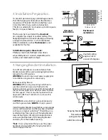
3.         Make sure you have a location selected for your fan that allows clear space for the blades to rotate, and at 

least seven (7) feet (2.13 meters) of clearance between the floor and the fan blade tips.  The fan should be 
mounted so that the tips of the blades are at least thirty (30) inches (76 centimeters) from walls or other 
upright structures.

4.         The outlet box and ceiling support joist used must be securely mounted, and capable of supporting at least 

35 pounds (16 kilograms).  The outlet box must be supported directly by the building structure.  Use only 
CUL (Canada) or UL (USA) listed outlet boxes marked "FOR FAN SUPPORT."

WARNING

:  To reduce the risk of fire, electrical shock, or personal injury, mount to the outlet box marked 

"Acceptable for Fan Support of 15.9 kg (35 lb) or less,"  and use the mounting screws provided with the outlet box.  
Most outlet boxes commonly used for the support of lighting fixtures are not acceptable for fan support and may 
need to be replaced.  Consult a qualified electrician if in doubt.

WARNING

:  To reduce the risk of fire, electrical shock, or personal injury, wire connectors provided with this fan are 

designed to accept only one 12 gauge house wire and two lead wires from the fan. If your house wire is larger than 
12 gauge or there is more than one house wire to connect to the corresponding fan lead wires, consult an 
electrician for the proper size wire connectors to use.

5.         Electrical diagrams are for reference only.  Light kits that are not packed with the fan must be CUL (Canada) or 

UL (USA) listed and marked suitable for use with the model fan you are installing.  Switches must be CUL 
(Canada) or UL (USA) general use switches.  Refer to the instructions packaged with the light kits and 
switches for proper assembly.

6.         After installation is complete, check that all connections are absolutely secure.
7.         After making electrical connections, spliced conductors should be turned upward and pushed carefully up 

into the outlet box.  The wires should be spread apart with the grounded conductor and the 
equipment-grounding conductor on opposite sides of the outlet box.

WARNING

:  To reduce the risk of fire or electrical shock, do not use this fan with any solid state speed control device 

or control fan speed with a full range dimmer switch.  [Using a full range dimmer switch to control fan speed will 
cause a loud humming noise from fan.]  

8.        Do not operate the reverse switch until fan has come to a complete stop.
9.        Do not insert anything between the fan blades while they are rotating.

WARNING

:  To reduce the risk of personal injury, do not bend the blade arms during assembly or after installation.  

Do not insert objects into the path of the blades.

WARNING

:  To avoid personal injury or damage to the fan and other items, be cautious when working around or 

cleaning the fan.

10.      Do not use water or detergents when cleaning the fan or fan blades. A dry dust cloth or lightly dampened 

cloth will be suitable for most cleaning.

WARNING

:  To reduce the risk of personal injury, use 

only

 parts provided with this fan.  

The use of parts OTHER 

than those provided with this fan will void the warranty.

NOTE

:  The important safety precautions and instructions appearing in the manual are not meant to cover all 

possible conditions and situations that may occur.  It must be understood that common sense and caution are 
necessary factors in the installation and operation of this fan.

Summary of Contents for MIDORO MO56

Page 1: ...rol Assembly pg 9 Automated Learning Process Activating Code pg 10 Remote Control Operation pg 10 Testing Your Fan pg 10 Troubleshooting pg 11 Warranty pg 11 Parts Replacements pg 11 net weight of fan 26 84 lb 12 2 kg READ THESE INSTRUCTIONS AND SAVE THEM FOR FUTURE USE E192641 Federal regulations require ceiling fans with light kits manufactured or imported after January 1 2009 to limit total wat...

Page 2: ...your house wire is larger than 12 gauge or there is more than one house wire to connect to the corresponding fan lead wires consult an electrician for the proper size wire connectors to use 5 Electrical diagrams are for reference only Light kits that are not packed with the fan must be CUL Canada or UL USA listed and marked suitable for use with the model fan you are installing Switches must be CU...

Page 3: ...ll control 2 pieces q plate 1 piece r remote control cover 1 piece s faceplate 3 pieces t hardware packs page 2 Carefully open the packaging Remove items from Styrofoam inserts Remove motor housing and place on carpet or Styrofoam to avoid damage to finish Do not discard fan carton or Styrofoam inserts should this fan need to be returned for repairs Check against parts inventory that all parts hav...

Page 4: ...utlet box screws flat washers Turn off circuit breakers to current fixture from breaker panel and be sure operating light switch is turned to the OFF position WARNING Failure to disconnect power supply prior to installation may result in serious injury Remove existing fixture WARNING When using an existing outlet box be sure the outlet box is securely attached to the building structure and can sup...

Page 5: ...usly removed Tighten yoke set screws and nuts securely Refer to diagram 2 Slide yoke cover and canopy over downrod Refer to diagram 3 Thread safety cable and wires through hanging ball then slide hanging ball over downrod the top of the downrod should be noted as having a set screw hole use this hole when setting the set screw Insert stop pin into top of downrod and raise hanging ball Be sure stop...

Page 6: ...l slot until it lines up with the hanging bracket tab WARNING Failure to align slot in hanging ball with tab in hanging bracket may result in serious injury or death Tip Seek the help of another person to hold the stepladder in place and to help lift the fan up to you once you are set on the ladder Find a secure attachment point wood ceiling joist highly recommended and secure safety cable It will...

Page 7: ...onnector separately with electrical tape as an extra safety measure Gently push wires and taped wire connectors into outlet box Install one 12 volt battery included in wall control IMPORTANT Wall control will not function unless battery is installed Since this fan comes with incandescent bulbs the dimmer switch labeled DIM and ON has been pre set to the ON position DIM If you do not wish to have d...

Page 8: ... can be set on each blade screw prior to installing blades Locate 15 blade attachment screws and washers in hardware pack Slide blade through one of the narrow rectangular openings on motor housing aligning holes in blade with holes in blade arm located on the underside of the motor housing refer to drawing at right Insert 3 blade attachment screws along with washers with fingers first and then ti...

Page 9: ...emoved and securely tighten all 3 screws with a Phillips screwdriver Refer to diagram 2 IMPORTANT Be careful when attaching threaded rod assembly that the wiring does not get pinched or caught under the metal edges Allow wires to come through corresponding openings in plate on threaded rod assembly Install 2 candelabra base 60 watt max bulbs included Important When replacing bulb s please allow bu...

Page 10: ... have dimming capability please move the switch to the OFF position ON OFF Refer to diagram 2 Attach black faceplate to front of wall control press down firmly Refer to diagram 3 Align holes in wall control with posts located on inside of TOP part of remote control cover and press together firmly Place wall control into BOTTOM part of remote control cover aligning posts in top of remote control co...

Page 11: ...ion ON OFF slider switch turns wall control ON or OFF switch not functional on handheld remote HIGH button turns fan to HIGH speed MED button turns fan to MEDIUM speed LOW button turns fan to LOW speed OFF button turns fan OFF L1 button not applicable for this fan L2 button turns light kit ON OFF when pressed once dims light kit when pressed and held down REV button used to REVERSE blade direction...

Page 12: ...ly 2 Check that wires in canopy are wired properly 3 Replace defective bulb with same type of bulb 4 Verify that molex connections in light kit fitter are connected properly Problem Fan and light fail to operate with wall control optional and or handheld remote control Solutions 1 Check battery power in handheld remote control 2 Learning process between fan handheld remote control and if applicabl...

Reviews: