
5. Fan Assembly. (cont.)
page 5
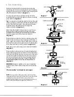
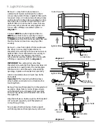
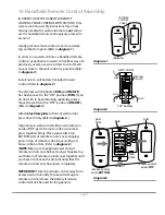
Install 4 candelabra base 25 watt max. bulbs
(included) in top of motor assembly.
Important:
When you need to replace bulbs,
please allow bulb(s) and glass shade(s) to cool
down before touching them.
Locate 8 glass housing support screws in
hardware pack. Gently slide glass housing into
motor assembly.
Attach glass housing to motor assembly with 1
glass housing support by aligning holes in glass
housing support with 2 holes on top of glass
housing. Before securing screws permanently,
repeat procedure with the remaining glass
housing supports.
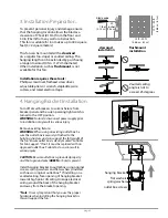
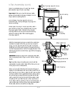
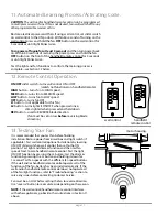
With the hanging bracket secured to the outlet box
and able to support the fan, you are now ready to
hang your fan. Grab the fan firmly with two hands.
Slide downrod through opening in hanging bracket
and let hanging ball rest on the hanging bracket. Turn
the hanging ball slot until it lines up with the hanging
bracket tab.
WARNING
: Failure to align slot in hanging ball with
tab in hanging bracket may result in serious injury or
death.
Tip:
Seek the help of another person to hold the
stepladder in place and to help lift the fan up to you
once you are set on the ladder.
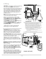
Find a secure attachment point (wood ceiling joist
highly recommended) and secure safety cable. It will
be necessary to use a heavy duty wood screw, washer
and lock washer (not supplied) with the safety cable
loop. If necessary, adjust the loop at the end of the
safety cable. The loop at the end of the safety cable
should just fit over the threads on the wood screw.
Test safety cable by pulling on loose end with pliers. If
safety cable slips, the loop must be adjusted tighter.
Extra cable slack can be left in ceiling area.
hanging ball slot
hanging bracket tab
motor housing
safety
cable
safety cable loop
canopy
wood
ceiling
joist
wood screw
and washer
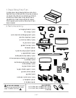
bulb
motor
assembly
glass housing
glass housing support
glass housing support screws


