
page 6
6. Wiring.
Modifications not approved by the party responsible for compliance
could void the user's authority to operate the equipment.
*NOTE: This equipment has been tested and found to comply with the limits for a Class B
digital device, pursuant to Part 15 of the FCC Rules. These limits are designed to provide
reasonable protection against harmful interference in a residential installation. This
equipment generates, uses and can radiate radio frequency energy and, if not installed and
used in accordance with the instructions, may cause harmful interference to
radio
communications. However, there is no guarantee that interference will not occur in a
particular installation. If this equipment does cause harmful interference to
radio
or television
reception, which can be determined by turning the equipment off and on, the user is
encouraged to try to correct the interference by one or more of the following measures:
* Reorient or relocate the receiving antenna.
* Increase the separation between the equipment and receiver.
* Connect the equipment into an outlet on a circuit different from that to which the
receiver is connected.
Consult the dealer or an experienced radio/TV technician for help.
black
black
white
white
black supply wire
ground
(green
or bare)
white supply wire
from
ceiling
from
fan
ground
(green or bare)
(wiring for fan)
*
[
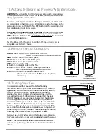
PLEASE NOTE
: Wall and/or handheld remote
control must be used for fan to operate.
If you do
not
wish to use the wall control, please proceed to
Section 7 below to continue with fan installation.
]
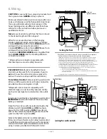
To install wall control
, remove existing wall switch.
Wire one of the
wall controls with wire connectors
provided
as shown in diagram at right.
*Wrap each wire connector separately with
electrical tape as an extra safety measure. Gently
push wires and taped wire connectors into outlet
box.
Install one 12-volt battery (included) in wall control.
IMPORTANT
: Wall control will not function unless
battery is installed.
Since this fan comes with incandescent bulbs, the
dimmer switch (labeled
DIM
and
ON
) has been
pre-set to the "ON" position (
DIM
). If you do not
wish to have dimming capability, please move the
switch to the "OFF" position (
ON
).
Select a faceplate (almond or white) and press
firmly onto front of wall control. Attach wall control
to outlet box and secure with screws from original
wall switch. Attach plate (included) to wall control
using 2 screws provided with the wall control.
(wiring for wall control)
black (OUT to fan)
green
black
(AC IN from
breaker box)
black
(TO POWER supply)
black
green/
green/
bare
bare
ground
ground
green/
bare
ground
outlet box
wall
control
face-
plate
12V battery
dimmer
switch
plate
1
1
-
2
2
-
DIM ON
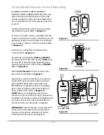
CAUTION
:
Be sure outlet box is properly grounded and
that a ground wire (
GREEN
or Bare) is present.
Make sure all electrical connections comply with Local
Codes or Ordinances and the National Electrical Code.
If you are unfamiliar with electrical wiring or if the
house/building wires are different colors than those
referred to in the instructions below, please use a
qualified electrician.
Note
:
Excess lead wire length from the fan can be cut
to the desired length and then stripped.
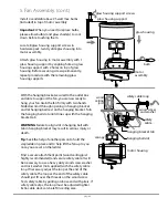
When fan is secured in place on the hanging
bracket, electrical wiring can be made as follows:
Connect
BLACK
wire from fan to
BLACK
wire from
ceiling with wire connector provided.
Connect
WHITE
wire from fan to
WHITE
wire from
ceiling with wire connector provided.
Connect all
GROUND
(
GREEN
) wires together from
fan to
BARE
/
GREEN
wire from ceiling with wire
connector provided.
* Wrap each wire connector separately with
electrical tape as an extra safety measure.


