background image

27

SERVICE AND MAINTENANCE

Drive Control Lever Stop Adjustment

When the drive control levers are both fully extended forward to the full-speed 
position and the tractor drifts left or right, the drive control lever stop adjustment 
can be adjusted to sync the wheel speeds. To perform the adjustment, proceed as 
follows:
1. 

Identify the side that the tractor is drifting to and adjust the opposite drive 
control lever. If the tractor drifts right, adjust the left control lever down 
(decrease speed) and vice versa.

2. 

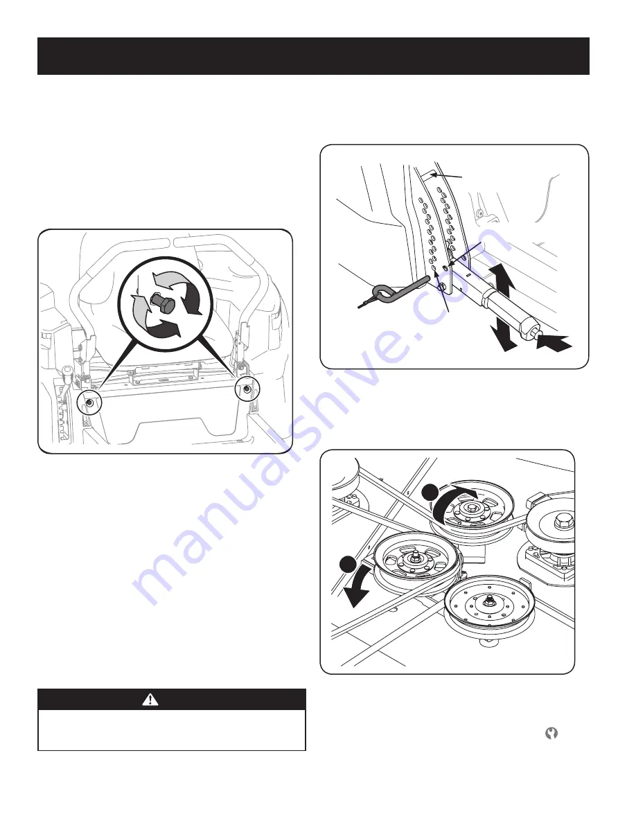
Locate the drive control lever stop adjustment bolts on the front of the seat 
frame. See Figure 23.

Figure 23

3. 

To decrease the forward speed, turn the bolt clockwise. To increase the 
forward speed, turn the bolt counter-clockwise. Turn the bolt in the 
necessary direction 

1⁄4

-turn at a time. After turning the bolt, check the 

adjustment by driving the tractor.

4. 

Continue the adjustment until the wheel speeds are in sync and the tractor 
drives straight with the drive control levers fully extended forward in the 
full-speed position.

Deck Removal

Remove the mower deck from the tractor as follows:
1. 

Move the tractor to a level surface, disengage the PTO, stop the engine, and 
set the parking brake.

2. 

Move the deck gauge wheels to their highest setting (lowest deck setting).

3. 

Remove the ‘V’ belt from the PTO pulley, located on the bottom of the 
engine, using one of the following two methods.

 WARNING

The muffler at the rear of the tractor may be extremely hot, and could 
cause serious burns. Use extreme caution when near the muffler. Allow the 
muffler to fully cool before removing the belt from the PTO pulley.

4. 

Releasing Belt Tension with the Idler Pulley

a.  Using the deck lift handle, raise the deck to the  position that provides 

the most horizontal run of the belt between the deck idler pulleys and 
the PTO pulley on the bottom of the engine. See Figure 24.

Transport Position/

Highest Mowing

Position

Lowest Mowing

Position

Deck Removal/

Installation Position

Figure 24

b.  Working from the middle of the tractor, pivot the idler bracket and 

movable idler pulley rearward away from the backside of the ‘V” belt 
(a) just far enough to lift the belt up and over the idler pulley (b). See 
Figure 25.

b

a

Figure 25

c. 

From beneath the rear of the tractor, slide the belt off of the PTO 
pulley on the bottom of the engine.

d.  Lower the deck into the deck removal/installation position 

 using the 

deck lift handle. See Figure 24.

e.  Skip ahead to step 6.

Summary of Contents for PRO series

Page 1: ...anagement Corporation Hoffman Estates IL 60179 U S A Visit our website www craftsman com CAUTION Before using this equipment read this manual and follow all safety rules and operating instructions 5 Safe Operation Practices 2 Slope Gauge 6 Assembly 7 Operation 11 Service and Maintenance 21 Troubleshooting 31 Español 33 Warranty Service See Separate Supplement NOTE This Operator s Manual covers sev...

Page 2: ... pay attention to the safety system function that stops power to the blades when driving in reverse If not functioning properly contact an authorized dealer for safety system inspection and repair Slow down before turning Operate the machine smoothly Avoid erratic operation and excessive speed Disengage blade s set parking brake stop engine and wait until the blade s come to a complete stop before...

Page 3: ...opes greater than 5 degrees When going down hill the extra weight tends to push the riding mower and may cause you to loose control e g riding mower may speed up braking and steering ability are reduced attachment may jack knife and cause riding mower to overturn CHILDREN Tragic accidents can occur if the operator is not alert to the presence of children Children are often attracted to the machine...

Page 4: ...ir proper operation regularly After striking a foreign object stop the engine disconnect the spark plug wire s and ground against the engine Thoroughly inspect the machine for any damage Repair the damage before starting and operating Never attempt to make adjustments or repairs to the machine while the engine is running Grass catcher components and the discharge cover are subject to wear and dama...

Page 5: ...R SAFETY DEVICES Keep safety devices guards shields switches etc in place and working WARNING BYSTANDERS Keep bystanders helpers children and pets at least 75 feet from the machine while it is in operation WARNING SLOPE OPERATION Do not operate this machine on a slope greater than 15 degrees Do not mow up and down slopes Mow across slopes no greater than 15 degrees Avoid sudden turns Use low speed...

Page 6: ...until the left corner touches the slope See Figure 1 and Figure 2 5 If there is a gap below the gauge the slope is too steep for safe operation See Figure 2 above 1 5 d a s h e d l i n e Figure 2 Figure 1 15 Slope 15 Slope WARNING Slopes are a major factor related to tip over and roll over accidents which can result in severe injury or death Do not operate machine on slopes in excess of 15 degrees...

Page 7: ...led out Return the rod to its normal position prior to operating the riding mower CAUTION Never attempt to move the riding mower manually without first opening the hydrostatic relief valve Doing so will result in serious damage to the riding mower s transmission Install Operator s Seat To install the seat proceed as follows NOTE The seat is shipped with the seat switch and seat pan attached 1 Cut ...

Page 8: ...djusting the Drive Control Levers in the Maintenance Adjustments for instructions on the final adjustment of the levers Connecting the Battery Cables WARNING Battery posts terminals and related accessories contain lead and lead compounds chemicals known to the State of California to cause cancer and reproductive harm Wash hands after handling CAUTION When attaching battery cables always connect th...

Page 9: ...d to support the weight of the cutting deck The mower deck cutting height can be set in any of six height settings using the riding mower s deck lift handle The deck heights range from 1 1 2 to 4 The deck gauge wheel position should be approximately 1 4 to 1 2 above the ground when the deck is set in the desired height setting Using the lift handle set the deck in the desired height setting then c...

Page 10: ...dfuelorfuelvapormayignite Ifanyfuelisspilled makesuretheareaisdrybeforestartingtheengine Avoid repeated or prolonged contact with skin or breathing of vapor Adding Fuel WARNING Use extreme care when handling gasoline Gasoline is extremely flammable and the vapors are explosive Never fuel the riding mower indoors or while the engine is hot or running Extinguish cigarettes cigars pipes and other sou...

Page 11: ...ither sit in the tractor seat or to dismount the tractor The levers must be fully opened out and in the neutral position to start the tractor engine When the levers are fully outward the parking brake is also engaged Each lever controls the respective RH or LH transmission Consequently these levers control all of the movements of the tractor Driving and steering utilizing these control levers is q...

Page 12: ...located on the RH console to the left of the hour meter indicator panel The PTO knob operates the electric PTO clutch mounted on the bottom of the engine crankshaft Pull the knob upward to engage the PTO clutch or push the knob downward to disengage the clutch The PTO knob must be in the disengaged position when starting the engine Transmission Bypass Rods The transmission bypass rods one for each...

Page 13: ...ith a greater incline present dangerous operating conditions Tractors can be rolled over Always mow across slopes never up and down the slope Avoid turning downhill if possible start at the bottom and work up to the top Use extra care and go slowly when turning downhill Control the speed and direction of the zero turn machine primarily with the speed directional control lap bar of the downhill sid...

Page 14: ...m comfort visibility and for maintaining complete control of the tractor Safety Interlock System This tractor is equipped with a safety interlock system for the protection of the operator If the interlock system should ever malfunction do not operate the tractor Contact your authorized service dealer Thesafetyinterlocksystempreventstheenginefromcrankingorstartingunless the RHandLHdrivecontrollever...

Page 15: ...ke control if equipped to the SLOW position and allow the engine to idle for about one minute 4 Turn the ignition key to the STOP position and remove the key from the ignition switch NOTE Always remove the key from the ignition switch to prevent accidental starting or battery discharge if the equipment is left unattended Practice Operation Initial Use Operating a zero turn tractor is not like oper...

Page 16: ... forward The tractor will start to move forward See Figure 2 Driving Forward Faster Slower Neutral Position Figure 2 2 As the control levers are pushed farther forward the speed of the tractor will increase 3 To slow the tractor move the controls lever rearward to attain the desired speed or move the levers to the neutral position to stop the tractor WARNING Always maintain your grasp on the drive...

Page 17: ...crease 3 To slow the tractor move the controls lever forward to attain the desired speed or move the levers to the neutral position to stop the tractor Turning While Driving Rearward To turn the tractor while driving rearward move the control levers as necessary so that one lever is forward of the other The tractor will turn in the direction of the forward control lever 1 To turn to the left while...

Page 18: ... top left corner of the key switch module will be ON while activated See Figure 8 4 Once activated indicator light ON the tractor can be driven in reverse with the cutting blades PTO engaged 5 Always look down and behind before and while backing to make sure no children are around After resuming forward motion return the key to the NORMAL MOWING position The REVERSE CAUTION MODE will remain activa...

Page 19: ...e downhill side of the tractor with the uphill control lever remaining essentially in a fixed position 2 Avoid turning downhill if possible Start at the bottom of a slope and work upward Always slow down before turning 3 Use extra care and go slowly when turning downhill Operating The PTO Operate the PTO clutch as follows NOTE During your units initial break in period in order to engage the PTO an...

Page 20: ...aged position Shut engine off and remove the key Doingsowillminimizethepossibilityofhavingyourlawn browned by hotexhaustfromyourtractor srunningengine Deck Lift Lever To raise or lower the cutting deck depressthebuttonontheendofthehandleand pushdownwardtolowerthedeck orpullupwardtoraisethedeck then place it in the hole best suited for your application To place the deck in the transport position li...

Page 21: ...ery terminals 2 Lubrication points 3 Blades 4 Tires 5 Front wheels 6 Deck 1 Clean 2 Grease 3 Check Sharpen Replace as needed 4 Check 5 Lube 6 Check Clean Every 25 hours 1 Deck wheels 2 Deck level pitch 3 Deck spindles 1 Inspect and lube 2 Check 3 Lube Every 50 hours 1 Belts and pulleys 2 Engine Oil 3 Oil Filter 4 Air Filter 5 Fuel Filter 1 Check for damage and wear 2 Change See engine manual 3 Rep...

Page 22: ...ppropriate oil collection container with at least a 2 5 quart capacity to collect the used oil 6 Once the oil has finished draining replace the square head hose plug and fill the engine as instructed in the engine owner s manual See engine owner s manual included with this tractor for oil capacity Tire Maintenance Check the tire air pressure after every 50 hours of operation or weekly Keep the tir...

Page 23: ...id tipping Even a sealed battery will leak electrolyte when tipped Battery Removal WARNING Battery posts terminals and related accessories contain lead and lead compounds Wash hands after handling The battery is located beneath the seat frame To remove the battery 1 Remove the hex washer screw securing the battery hold down bracket to the frame Then flip the battery hold down bracket up to free th...

Page 24: ...k Deck Wash Nozzle Figure 17 4 Turn on the water supply 5 From the riding mower operator s seat start the engine and engage the PTO Allow to run as needed Disengage the PTO and stop the engine 6 Turn off the water supply 7 Pull back the lock collar of the nozzle adapter to disconnect the adapter from the nozzle Hydrostatic Transmission Your zero turn tractor is equipped with dual integrated hydros...

Page 25: ...me position Adjust so that both levers are even with each other when in the neutral position Deck Leveling NOTE Check the tractor s tire pressure before performing any deck leveling adjustments Refer to Tires for information regarding tire pressure WARNING Shut the engine off remove the ignition key and engage the parking brake before making adjustments Protect your hands by using heavy gloves whe...

Page 26: ...uld not ride on the ground The front gauge wheels should be approximately 1 4 1 2 above the ground when the deck is set in the desired height setting Using the deck lift handle set the deck in the desired height setting then check the gauge wheel distance from the ground below If necessary adjust the front gauge wheels as follows 1 Visually check the distance between the front gauge wheels and the...

Page 27: ...as follows 1 Move the tractor to a level surface disengage the PTO stop the engine and set the parking brake 2 Move the deck gauge wheels to their highest setting lowest deck setting 3 Remove the V belt from the PTO pulley located on the bottom of the engine using one of the following two methods WARNING The muffler at the rear of the tractor may be extremely hot and could cause serious burns Use ...

Page 28: ...the decktothedecklifthandleandsnapback 7 Slide the front deck lift rod off the hanger brackets on the front of the deck 8 Place the deck lift handle into the highest mowing position and slide the deck out from the right side of the tractor Deck Installation Install the deck on the tractor as follows 1 PlacethedecklifthandleinthehighestmowingpositionSeeFigure24 2 Slide the deck under the tractor on...

Page 29: ...ebelthasbeenroutedproperly Replacing the Belt 1 Remove the deck from beneath the tractor refer to Deck Removal 2 Remove the hex washer screws securing the belt covers to the deck See Figure 28 Figure 28 3 Remove the two idler pulleys by removing the hex screws washers and flange lock nuts that secure them to the deck and the idler arm See Figure 29 Do not lose any of the hardware when removing the...

Page 30: ... the riding mower refer to Deck Removal then gently flip the deck over to expose its underside 2 Use a 1 1 8 wrench to hold the hex nut on top of the spindle assembly when loosening the hex nut securing the blade A block of wood may be placed between the deck housing and the cutting edge of the blade to help in breaking loose the hex nut securing the blade See Figure 31 Figure 31 3 When reinstalli...

Page 31: ...Engage parking brake 3 Connect wire to spark plug 4 Place Throttle lever to FAST position 5 Fill tank with clean fresh less than 30 days old gas 6 Replace fuel line See a Sears or other qualified service dealer Replace fuel filter See the Service and Maintenance section 7 Clean adjust gap or replace plug 8 Crank engine with throttle in FAST position 9 Replace fuse Engine runs erratically 1 Riding ...

Page 32: ...ark plug and adjust gap Engine idles poorly 1 Fouled spark plug 2 Dirty air cleaner 1 Replace spark plug and adjust gap 2 Clean or replace air cleaner element and or clean pre cleaner Excessive vibration 1 Cutting blades loose or unbalanced 2 Damaged dull or bent cutting blade 1 Tighten blade and spindle Balance blade 2 Replace blade Uneven cut 1 Deck not leveled properly 2 Dull blade 3 Uneven tir...

Page 33: ...a que se ilustra aquí puede diferir de la suya Último dígito del número de modelo varía Para obtener respuestas a sus preguntas acerca de este producto llame al 1 888 331 4569 Atención al Cliente Línea Caliente Este producto tiene un motor de bajas emisiones que funciona de forma diferente de los motores previamente construidas Antes de arrancar el motor lea y comprenda el Craftsman manual del ope...

Page 34: ...le el funcionamiento del sistema de seguridad que corta la energía de las cuchillas al conducir marcha atrás Si no funciona correctamente póngase en contacto con un distribuidor autorizado para que se inspeccione y repare el sistema de seguridad Reduzca la velocidad antes de girar Haga funcionar la máquina de manera uniforme Evite funcionar de manera errática y a excesiva velocidad Desacople las c...

Page 35: ...ndientes de más de 5º Cuando se desplaza pendiente abajo el peso adicional tiende a empujar el tractor cortacésped y puede hacer que se pierda el control del mismo por ejemplo el tractor cortacésped se puede acelerar se reduce la capacidad para frenar y maniobrar los accesorios pueden plegarse como un cortaplumas y hacer que el tractor vuelque NIÑOS Pueden ocurrir accidentes trágicos si el operado...

Page 36: ...re el sistema de bloqueo de seguridad u otros dispositivos de seguridad Controle periódicamente que funcionen correctamente Después de golpear algún objeto extraño detenga el motor desconecte los cables de la bujía y conéctelo a tierra con el motor Inspeccione minuciosamente la máquina para ver si está dañada Repare el daño antes de volver a arrancar y operar la máquina Nunca intente hacer ajustes...

Page 37: ...guridad guardas protectores interruptores etc en su lugar y funcionando ADVERTENCIA OBSERVADORES Mantenga a los observadores ayudantes mascotas y niños por lo menos a 75 pies de la máquina siempre que esté funcionando ADVERTENCIA OPERACIÓN EN PENDIENTE No opere esta máquina en una pendiente superior a 15 grados No corte de arriba a abajo laderas Corte el césped a través de pendientes no superiores...

Page 38: ... DETERMINAR SI UNA PENDIENTE ES DEMASIADO ESCARPADO PARA UNA OPERACIÓN SEGURA Para comprobar la pendiente haga lo siguiente 1 Borrar esta página y doble a lo largo de la línea discontinua 2 Localizar un objeto vertical sobre o detrás de la pendiente un poste un edificio una valla un árbol etc 3 Alinee cada lado de pendiente de calibre con el objeto vertical consultar Figura 1 and Figura 2 4 Ajuste...

Page 39: ...uera Regrese la varilla a su posición normal antes de usar el tractor cortacésped PRECAUCIÓN No intente nunca mover el tractor cortacésped manualmente sin abrir primero la válvula de descarga hidrostática De hacerlo puede dañarse gravemente la transmisión del tractor Instale el asiento del operador Para instalar el asiento proceda de la siguiente manera NOTA El asiento se envía con el interruptor ...

Page 40: ...ucciones para el ajuste final de las palancas en la Sección de Mantenimiento y Ajustes bajo el título Ajuste de las palancas de control de la transmisión Conexión de los cables de la batería ADVERTENCIA Los bornes los terminales y los accesorios relacionados de la batería contienen plomo y compuestos de plomo sustancias químicas que según lo establecido por el Estado de California causan cáncer y ...

Page 41: ... la plataforma de corte La altura de corte de la plataforma de corte se puede fijar en cualquiera de seis valores de altura usando la manija de elevación de la plataforma del tractor Las alturas de la plataforma oscilan entre 1 1 2 hasta 4 La posición de las ruedas de calibración de la plataforma debe ser aproximadamente entre 1 4 a 1 2 por encima del nivel del suelo cuando la plataforma se fija e...

Page 42: ...ese de que el área esté seca antes de arrancar el motor Evite el contacto repetido o prolongado con la piel y la inhalación de los vapores Carga de combustible ADVERTENCIA Tenga mucho cuidado al trabajar con gasolina La gasolina es sumamente inflamable y sus vapores pueden causar explosiones Nunca agregue combustible al tractor cortacésped en interiores ni mientras el motor está caliente o en func...

Page 43: ...ierto para permitir al operador sentarse en el asiento del tractor o descender del mismo Las palancas deben estar totalmente abiertas y en posición neutra para arrancar el motor del tractor Cuando las palancas están completamente hacia afuera también se activa el freno de mano Cada palanca controla la transmisión respectiva del lado derecho o del lado izquierdo En consecuencia estas palancas contr...

Page 44: ...o a la izquierda del medidor horario panel indicador La perilla de la toma de fuerza PTO hace funcionar el embrague eléctrico de toma de fuerza PTO que está montado en la base del cigüeñal del motor Tire de la perilla del interruptor hacia arriba para engranar el embrague de la toma de fuerza PTO o empuje la perilla hacia abajo para desengranar el embrague Al arrancar el motor la perilla de la tom...

Page 45: ...inación presentan condiciones de operación peligrosas Los tractores pueden voltearse Siempre conduzca el tractor de forma transversal a la pendiente nunca hacia arriba y hacia abajo En lo posible evite girar cuesta abajo arranque abajo y trabaje sin detenerse hasta la parte más alta Ponga especial cuidado y conduzca lentamente al girar cuesta abajo Controle la velocidad y la dirección de la máquin...

Page 46: ...ento 13 Ajuste el asiento para la mayor comodidad del operador para una adecuada visibilidad y para mantener el control completo del tractor Sistema de bloqueo de seguridad Este tractor está equipado con un sistema de bloqueo de seguridad para protección del operador Si el sistema de bloqueo funciona mal no se debe hacer funcionar el tractor Póngase en contacto con su distribuidor autorizado El si...

Page 47: ...ue el motor funcione al ralentí durante aproximadamente un minuto 4 Gire la llave de encendido a la posición STOP parada y quite la llave del interruptor de encendido NOTA Siempre quite la llave del interruptor de encendido para evitar el arranque accidental o la descarga de la batería si el equipo queda sin supervisión Practique el modo de operación con el tractor uso inicial Operar un tractor co...

Page 48: ...ra 11 Conducción hacia adelante Más rápido Más despacio Posición de punto muerto Figura 11 2 A medida que las palancas de control se empujan más hacia adelante aumenta la velocidad del tractor 3 Para que el tractor se desplace más lentamente mueva la palanca de control hacia atrás hasta alcanzar la velocidad deseada o coloque las palancas en la posición de punto muerto para detener el tractor ADVE...

Page 49: ...e hasta alcanzar la velocidad deseada o coloque las palancas en la posición de punto muerto para detener el tractor Realizar un giro mientras se conduce marcha atrás Para que el tractor gire mientras se desplaza hacia atrás mueva las palancas de control según sea necesario para que una palanca quede más adelante que la otra El tractor girará en la dirección de la palanca que queda más adelante 1 P...

Page 50: ...da ON mientras esté activado Vea la Figura 17 4 Una vez activada luz indicadora ENCENDIDA el tractor podrá operar en marcha atrás con las cuchillas de corte PTO acopladas 5 Siempremirehaciaabajoyhaciaatrásantesymientrassedesplazamarchaatrás para verificarquenohayaniñoscerca Unavezretomadoelmovimientohaciaadelante vuelvaacolocarlallaveenlaposiciónNORMALMOWING cortenormal El MODO DE PRECAUCIÓN EN MA...

Page 51: ...l del lado del tractor que queda cuesta abajo mientras que la palanca de control del lado cuesta arriba permanece esencialmente fija 2 En lo posible evite girar cuesta abajo Comience en la base de la pendiente y opere cuesta arriba Siempre reduzca la velocidad antes de dar la vuelta 3 Ponga especial cuidado y conduzca lentamente al girar cuesta abajo Funcionamiento de la toma de fuerza PTO Opere e...

Page 52: ...e su césped resulte quemado por el escape caliente del motor en funcionamiento Palanca de elevación de la plataforma Para levantar o bajar la plataforma de corte oprima el botón que está en el extremo de la manija y empújela hacia abajo para bajar la plataforma o tire hacia arriba para levantarla luego ubíquela en el orificio más adecuado para su aplicación Para ubicar la plataforma en la posición...

Page 53: ...Ruedas delanteras 6 Plataforma 1 Limpiar 2 Engrasar 3 Verificar Afilar Reemplazarsegúnseanecesario 4 Verificar 5 Lubricar 6 Verificar Limpiar Cada 25 horas 1 Ruedas de la plataforma 2 Nivel inclinación de la plataforma 3 Husillos de plataforma 1 Inspeccionar y lubricar 2 Verificar 3 Lubricar Cada 50 horas 1 Correas y poleas 2 Aceite del motor 3 Filtro de aceite 4 Filtro de aire 5 Filtro de combust...

Page 54: ...pósito de recolección de aceite adecuado que posea una capacidad de por lo menos 2 5 cuartos de galón 2 4 litros para recoger el aceite usado 6 Una vez que se haya terminado de drenar el aceite reemplace el tapón de manguera de cabeza cuadrada y llene el motor como se indica en el manual del propietario del motor Para conocer la capacidad de aceite consulte el manual del propietario del motor que ...

Page 55: ... inclina Retiro de la batería ADVERTENCIA Los postes bornes y accesorios de la batería contienen plomo y compuestos de plomo Lávese las manos después de estar en contacto con estos componentes La batería está ubicada debajo del marco del asiento Para retirar la batería 1 Extraiga el tornillo de la arandela hexagonal que sujeta el soporte de sujeción de la batería al marco TLuego levante el soporte...

Page 56: ...Figura 26 4 Abra el suministro de agua 5 Desde el asiento del operador del tractor cortacésped encienda el motor y active la toma de fuerza PTO Deje funcionar según sea necesario Desactive la toma de fuerza PTO y detenga el motor 6 Cierre el suministro de agua 7 Tire del collarín de ajuste del adaptador del pico hacia atrás para desconectar el adaptador del pico Transmisión hidrostática Su tractor...

Page 57: ...ustar la otra palanca de control en la misma posición Ajuste de manera que las dos palancas queden parejas entre sí cuando se encuentran en posición neutra Nivelación de la plataforma NOTA Controle la presión de neumáticos del tractor antes de realizar cualquier nivelación de la plataforma Consulte la sección Neumáticos para obtener información sobre la presión de los neumáticos ADVERTENCIA Apague...

Page 58: ... cuidado del césped y no se deben usar para desplazarse sobre el piso La posición de las ruedas de calibración delanteras de la plataforma debe ser aproximadamente entre 1 4 1 2 por encima del nivel del suelo cuando la plataforma se fija en el valor de altura deseado Usando la manija de elevación de la plataforma fije la plataforma en el valor de altura deseado luego controle la distancia entre la...

Page 59: ... la plataforma Retire la plataforma de corte del tractor de la siguiente forma 1 Desplace el tractor a una superficie nivelada desconecte la PTO pare el motor y ponga el freno de mano 2 Mueva las ruedas de calibración de la plataforma a su ajuste más alto ajuste más bajo de la plataforma 3 Retire la correa en V de la polea de la toma de fuerza PTO ubicada en la base del motor usando uno de los dos...

Page 60: ...RECAUCIÓN Hayciertatensióndelosresortesdebidoalpesodelaplataforma Alretirarelvarillaje deelevacióndelaplataforma latensióndelosresortespasarádelaplataformaala manijadeelevacióndeplataformayretrocederáasuposiciónoriginal 7 Deslice la varilla de elevación de la plataforma delantera para sacarla de las ménsulas de suspensión del frente de la plataforma 8 Ubique la manija de elevación de la plataforma...

Page 61: ...ndoyrotandolapoleaylacorreahastaquelacorrease enrolletotalmenteenlapoleadelaPTO NOTA Antesdeusareltractor compruebelainstalacióndelacorreaparaestar segurodequelamismasehacolocadocorrectamente Cambio de la correa 1 Extraiga la plataforma de la parte inferior del tractor consulte la sección Extracción de la plataforma 2 Retire los tornillos de arandela hexagonal que sujetan las cubiertas de las corr...

Page 62: ...ortacésped consulte la sección Extracción de la plataforma luego voltee con delicadeza la plataforma para dejar al descubierto su parte inferior 2 Use una llave de 1 1 8 para sostener la tuerca hexagonal en la parte superior del conjunto del husillo cuando afloje la tuerca hexagonal que fija la cuchilla Se puede colocar un bloque de madera entre el alojamiento de la plataforma y el borde de corte ...

Page 63: ...FAST velocidad rápida 5 Llene el depósito con gasolina limpia y nueva que tenga menos de 30 días 6 Vuelva a colocar la línea de combustible Comuníquese con Sears u otro distribuidor de servicio calificado Reemplace el filtro de combustible Consulte la sección Servicio y Mantenimiento 7 Limpie ajuste la separación o cambie la bujía 8 Arranque el motor con el acelerador en posición FAST velocidad rá...

Page 64: ... El motor funciona mal en marcha lenta 1 La bujía de encendido está sucia 2 El depurador de aire está sucio 1 Extraiga la bujía y regule la separación 2 Limpie o reemplace el elemento del depurador de aire y o limpie el prefiltro Vibración excesiva 1 Cuchillas de corte flojas o descentradas 2 Cuchilla dañada desafilada o doblada 1 Apriete la cuchilla y el husillo Equilibre la cuchilla 2 Reemplace ...

Reviews: