background image

33

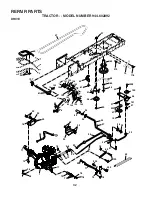
REPAIR PARTS

TRACTOR - - MODEL NUMBER 944.602892

DRIVE

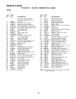
KEY    PART             
NO.     NO.                DESCRIPTION

KEY    PART             
NO.     NO.                DESCRIPTION

NOTE:


All component dimensions given in U.S. inches

             1 inch = 25.4 mm

1         - - - - - -          Transaxle (See Breakdown)
                                 Hydro Gear Model 314-0510
8         165866           Rod Shift 
10       STD561210   Pin Cotter  1/8 x 1 CAD
14       10040400       Washer Lock Hvy. Helical
15       74490544       Bolt, Hex FLGHD 5/16-18 Gr. 5
16       STD541431   Nut Lock Hex W/Ins  5/16-18 Unc 
19       STD541437   Nut Lock Hex W/Wsh  3/8-16 Unc
21       130564           nob, Deluxe  1/2-13
22       169498           Rod, Brake Hydro
24       STD541273   Nut
25       106888X        Spring, Brake Rod
26       STD551037   Washer
27       STD561210   Pin Cotter  1/8 x 3/4 CAD.
28       175765           Rod, Parking Brake
29       71673             Cap, Parking Brake
30       169592           Bracket, Transaxle
32       STD523107   Bolt Hex Hd  5/16-18 Unc x 3/4
34       175578           Shaft, Foot Pedal Nibbed
35       120183X        Bearing, Nylon
36       STD551062   Washer
37       STD571810   Pin, Roll
38       179114           Pulley, Idler, Flat Composite
39       74760648       Bolt Fin Hex 3/8-16unc x 3
41       175556           Keeper, Belt Retainer
47       127783           Pulley, Idler, V-Groove
48       154407           Bellcrank Clutch Grnd Drv STL
49       123205X        Retainer, Belt
50      

72110612

      Bolt Carr. Sh  3/8-16 x 1-1/2 Gr. 5

51       STD541437   Nut Crownlock  3/8-16 UNC
52       STD541431   Nut Crownlock  5/16-18 UNC
53       105710X        Link, Clutch
55       105709X        Spring, Return, Clutch
56       17060620       Screw 3/8-16  x 1-1/4
57       140294           V-Belt, Ground Drive
59       169691           Keeper, Center Span
61       17120614       Screw 3/8-16 x .875
62       8883R            Cover, Pedal
63       175410           Pulley, Engine
64       71170764       Bolt, Hex
65       STD551143   Washer

66       154778           Keeper Belt Engine 
70       134683           Keeper Belt Engine
71       169183           Strap Torque Lh Hydro 
73       169182           Strap Torque Rh Hydro 
74       137057           Spacer, Split
75       121749X        Washer  25/32 x 1-1/4 x 16 Gauge
76       STD581075   E-Ring
77       123583X        Key, Square
78       121748X        Washer  25/32 x 1-5/8 x 16 Gauge
81       165596           Shaft Asm. Cross 
82       165711           Spring Torsion
83       19171216       Washer  17/32 x 3/4 x 16 Ga.
84       169594           Link, Transaxle
89       164890X428  Console, Shift
90       124346X        Nut Self Thd Wsh-Hd  1/4 Zinc
95       170201           Control Asm Bypass Hydro
96       STD624003   Retainer Spring 1" Zinc/Cad
116     72140608       Bolt Rdhd Sq. Neck  3/8-16 x 1
120     73900600       Nut Lock Flg 3/8-16 UNC
151     19133210       Washer  13/32 x 2 x 10 Ga.
150     175456           Spacer Retainer
156     166002           Washer Srrted  5/16 ID x 1 x .125
158     165589           Bracket Shift Mount
159    

183900

          Hub Tapered Flange Shift LT

161     72140406       Bolt Rdhd Sqnk  1/4-20 x 3/4 Gr. 5
162     73680400       Nut Crownlock  1/4-20 Unc 
163     74780416       Bolt Hex Fin  1/4-20 Unc x 1 Gr. 5
164     19091010       Washer  5/8 x .281 x 10 Ga.
165     165623           Bracket Pivot Lever
166     166880           Screw   5/16-18 x 5/8
168     165492           Bolt Shoulder  5/16-18 x .561
169     165580           Plate Fastening LT
197     169613           Nyliner Snap-In 5/8" ID
198     169593           Washer Nyl 7/8" ID x .105"
199     169612           Bolt Shoulder 5/16-18 Unc
200     72140508       Bolt Rdhd Sqnk 5/16-18 Unc x 1
202     72110614       Bolt Carr Sh 3/8-16 x 1-3/4 Gr. 5
212     145212           Nut Hex Flange Lock
250     17060612       Screw  3/8-16 x 3/4
 

Summary of Contents for Sears 944.602892

Page 1: ...CTOR Important Read and follow all Safety Rules and Instructions Before Operating This Equipment MODEL NO 944 602892 OWNER S MANUAL Assembly Operation Maintenance Service and Adjustments Repair Parts Sears Canada Inc Toronto Ontario M5B 2B8 00011 02494 ...

Page 2: ...nges in speed or direction Avoid starting or stopping on a slope If tires lose traction disengage the blades and proceed slowly straight down the slope Safe Operation Practices for Ride On Mowers IMPORTANT THIS CUTTING MACHINE IS CAPABLE OF AMPUTATING HANDS AND FEET AND THROWING OBJECTS FAILURE TO OBSERVE THE FOLLOWING SAFETY INSTRUCTIONS COULD RESULT IN SERIOUS INJURY OR DEATH SAFETY RULES DO NOT...

Page 3: ... and turn machine off if children enter the area Before and when backing look behind and down for small children Mow up and down slopes 15 Max not across Remove obstacles such as rocks tree limbs etc Watchforholes ruts orbumps Uneventerraincouldoverturn the machine Tall grass can hide obstacles Use slow speed Choose a low gear so that you will not have to stop or shift while on the slope Avoid sta...

Page 4: ...ed it should be maintained in effective working order by the operator A spark arrester for the muffler is available through your nearestauthorizedservicecenter department SeeREPAIR PARTS section of this manual LIMITED TWO 2 YEAR WARRANTY ON CRAFTSMAN TRACTOR RIDING EQUIPMENT For two 2 years from date of purchase Sears Canada Inc will repair or replace at Sears option free of charge parts which are...

Page 5: ... Steering Wheel Insert 1 Large Flat Washer Steering Boot Steering Extension Shaft Steering Wheel Adapter 1 Knob 1 Washer 17 32 x 1 3 16 x 12 Gauge Seat Battery 2 Keys Slope Sheet Keys 1 Oil Drain Tube 1 Large Flat Washer 1 Hex Bolt 1 4 28 x 1 1 4 1 Locknut 1 4 28 1 Locknut 1 2 20 ...

Page 6: ...tch bands rings etc Positive terminal must be connected firsttopreventsparkingfromaccidental grounding Lift hood to raised position Openterminalaccessdoors removeterminalprotective caps and discard BEFORE REMOVINGTRACTOR FROM SKID ATTACH STEERING WHEEL See Fig 1 ASSEMBLE EXTENSION SHAFT AND BOOT Slide extension shaft onto lower steering shaft Align mounting holes in extension and lower shafts and ...

Page 7: ...d sit in seat Slide seat until a comfortable position is reached which allows you to press clutch brake pedal all the way down Get off seat without moving its adjusted position Raise seat and tighten adjustment knob securely ADJUSTMENT KNOB FLAT WASHER SEAT PAN SHOULDER BOLTS SEAT NOTE You may now roll or drive your tractor off the skid Follow the appropriate instruction below to remove the tracto...

Page 8: ...s important for best cutting performance Reduce tire pressure to PSI shown in PRODUCT SPECIFICATIONS section of this manual FIG 4 INSTALL MULCHER PLATE If previously removed See Fig 4 Raise and hold deflector shield in upright position Place front of mulcher plate over front of mower deck opening and slide into place as shown Hook front latch into hole on front of mower deck Hook rear latch into h...

Page 9: ...could result in serious injury or death The safety alert symbol is used to identify safety inform ation about hazards which can result in death serious injury and or property damage DANGER indicates a hazard which if not avoided will result in death or serious injury WARNING indicates a hazard which if not avoided could result in death or serious injury CAUTION indicates a hazard which if not avoi...

Page 10: ...the tractor and starting the engine PARKINGBRAKE Locksclutch brakepedalintothebrake position FREEWHEEL CONTROL Disengages transmission for pushing or slowly towing the tractor with the engine off AMMETER Indicates charging or discharging of battery MOTION CONTROL LEVER Selects the speed and direction of tractor ATTACHMENT LIFT LEVER Used to raise lower and adjust the mower deck or other attachment...

Page 11: ...w position and allowing engine to idle before stopping may cause engine to backfire Turn ignition key to OFF position and remove key Always remove key when leaving tractor to prevent unauthorized use Never use choke to stop engine PARKING BRAKE ENGAGED POSITION MOTION CONTROL LEVER THROTTLE CONTROL IGNITION KEY DISENGAGED POSITION ATTACHMENT CLUTCH LEVER ENGAGED POSITION CLUTCH BRAKE PEDAL DRIVE P...

Page 12: ...e ground and cause you to lose control of your tractor FIG 7 3 8 16 LOCKNUT 3 8 WASHER GAUGE WHEEL SHOULDER BOLT GUAGE WHEEL MOUNTING BRACKET TO TRANSPORT See Figs 5 and 9 When pushing or towing your tractor be sure to disengage transmission by placing freewheel control in freewheeling position Free wheel control is located at the rear drawbar of tractor Raiseattachmentlifttohighestpositionwithatt...

Page 13: ...iod after the transmission has been warmed up and may require the choke control be pulled out slightly NOTE If at a high altitude above 3000 feet or in cold temperatures below 32 F the carburetor fuel mixture may need to be adjusted for best engine performance See TO ADJUST CARBURETOR in the Service and Adjustments section of this manual BEFORE STARTING THE ENGINE CHECK ENGINE OIL LEVEL The engine...

Page 14: ...nished See Fig 10 If grass is extremely tall it should be mowed twice to reduce load and possible fire hazard from dried clip pings Make first cut relatively high the second to the desired height Do not mow grass when it is wet Wet grass will plug mower and leave undesirable clumps Allow grass to dry before mowing OPERATION Place tractor safely on level surface with engine off and parking brake se...

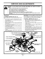
Page 15: ...Engine Oil without oil filter 1 2 GENERAL RECOMMENDATIONS The warranty on this tractor does not cover items that have beensubjectedtooperatorabuseornegligence Toreceive full value from the warranty operator must maintain tractor as instructed in this manual Some adjustments will need to be made periodically to properly maintain your tractor All adjustments in the Service and Adjustments section of...

Page 16: ...nance BRAKE OPERATION If tractor requires more than six 6 feet stopping distance at high speed in highest gear then brake must be adjusted See TOADJUSTBRAKE intheServiceandAdjustments section of this manual TIRES Maintainproperairpressureinalltires See PRODUCT SPECIFICATIONS section of this manual Keep tires free of gasoline oil or insect control chemi cals which can harm rubber Avoid stumps stone...

Page 17: ... the tractor is not used for 25 hours in one year Check the crankcase oil level before starting the engine and after each eight 8 hours of operation Tighten oil fill cap dipstick securely each time you check the oil level STARTING TEMPERATURE RANGE ANTICIPATED BEFORE NEXT OIL CHANGE SAE VISCOSITY GRADES 20 20 10 10 30 20 20 30 40 0 0 40 80 100 F C 32 60 30 Synthetic 5W 30 10W 30 5W 30 10W 30 C ERT...

Page 18: ...m overheating Clean with a wire brush or compressed air to remove dirt and stubborn dried gum fibers CLEAN AIR INTAKE COOLING AREAS To insure proper cooling make sure the grass screen cooling fins and other external surfaces of the engine are kept clean at all times Every 100 hours of operation more often under extremely dusty dirty conditions remove the blower housing and other cooling shrouds Cl...

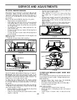
Page 19: ...ings Disconnect front links from deck by removing retainer springs Raise lift lever to raise suspension arms Slide mower out from under tractor IMPORTANT IF AN ATTACHMENT OTHER THAN THE MOWER DECK IS TO BE MOUNTED ON THE TRAC TOR REMOVE THE FRONT LINKS AND HOOK THE CLUTCH SPRING INTO SQUARE HOLE IN FRAME TO INSTALL MOWER See Fig 18 Raise attachment lift lever to its highest position Slide mower un...

Page 20: ...SO MOWER WILL STAY LEVEL SIDE TO SIDE To obtain the best cutting results the mower housing should be adjusted so that the front is approximately 1 8 to 1 2 lower than the rear when the mower is in its high est position Checkadjustmentonrightsideoftractor Measuredistance D directly in front and behind the mandrel at bottom edge of mower housing as shown Before making any necessary adjustments check...

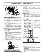
Page 21: ...TROL LEVER NEUTRAL ADJUSTMENT See Fig 26 The motion control lever has been preset at the factory and adjustment should not be necessary Loosen adjustment bolt in front of the right rear wheel and lightly tighten Start engine and move motion control lever until tractor does not move forward or backward Holdmotioncontrolleverinthatpositionandturnengine off TO REPLACE MOTION DRIVE BELT See Fig 25 Par...

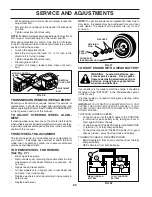
Page 22: ...deck height to the lowest position After above adjustment is made if the tractor still creeps forward or backward while motion control lever is in neutral position follow these steps Loosen the adjustment bolt Move the motion control lever 1 4 to 1 2 inch in the direction it is trying to creep Tighten adjustment bolt securely Start engine and test If tractor still creeps repeat above steps until s...

Page 23: ...eed as follows With engine not running move choke control located on dash panel to full choke position Loosen knob and remove cover assembly from air cleaner Chokeshouldbeclosed Ifitisnot loosencasingclamp screw and move choke cable until choke is completely closed Tighten casing clamp screw securely Replace air cleaner cover assembly and tighten knob TO ADJUST CARBURETOR Your carburetor is not ad...

Page 24: ...AL FUEL SYSTEM PARTS SUCH AS CARBURETOR FUEL FILTER FUEL HOSE OR TANK DURING STORAGE ALSO EXPERIENCE INDICATES THAT ALCOHOL BLENDED FUELS CALLED GASOHOL OR USING ETHANOLORMETHANOL CANATTRACTMOISTUREWHICH LEADSTOSEPARATIONANDFORMATIONOFACIDSDURING STORAGE ACIDIC GAS CAN DAMAGE THE FUEL SYSTEM OF AN ENGINE WHILE IN STORAGE Drain the fuel tank Start the engine and let it run until the fuel lines and ...

Page 25: ...heck replace ignition switch 8 Faulty solenoid or starter 8 Check replace solenoid or starter 9 Faulty operator presence switch es 9 Contact an authorized service center department Engine clicks but will not 1 Weak or dead battery 1 Recharge or replace battery start 2 Corroded battery terminals 2 Clean battery terminals 3 Loose or damaged wiring 3 Check all wiring 4 Faulty solenoid or starter 4 Ch...

Page 26: ...rpen blade Tighten blade bolt 7 Buildup of grass leaves and trash under mower 7 Clean underside of mower housing 8 Mower drive belt worn 8 Replace mower drive belt 9 Blades improperly installed 9 Reinstall blades sharp edge down 10 Improper blades used 10 Replace with blades listed in this manual 11 Clogged mower deck vent holes from buildup of 11 Clean around mandrels to open vent holes grass lea...

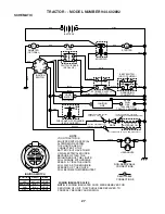
Page 27: ...OUR TRACTOR IS EQUIPPED WITH A SPECIAL ALTERNATOR SYSTEM THE LIGHTS ARE NOT CONNECTED TO THE BATTERY BUT HAVE THEIR OWN ELECTRICAL SOURCE BECAUSE OF THIS THE BRIGHTNESS OF THE LIGHTS WILL CHANGE WITH ENGINE SPEED AT IDLE THE LIGHTS WILL DIM AS THE ENGINE IS SPEEDED UP THE LIGHTS WILL BECOME THEIR BRIGHTEST WIRING INSULATED CLIPS NOTE IF WIRING INSULATED CLIPS WERE REMOVED FOR SERVICING OF UNIT THE...

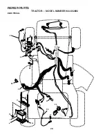
Page 28: ...28 REPAIR PARTS TRACTOR MODEL NUMBER 944 602892 ELECTRICAL 28 29 26 24 42 43 27 27 25 41 27 27 40 33 30 52 D C AM PE RE S 45 12 12 11 10 8 2 1 27 55 16 22 21 16 ...

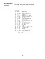
Page 29: ...W 4152J 22 4152J Bulb Light 1156 24 4799J Cable Battery 6 Ga 11 red 25 146148 Cable Battery 6 Ga w 16 ire red 26 175158 Fuse 27 73510400 Nut Keps Hex 1 4 20 Unc 28 145491 Cable Ground 6 Ga 21 black 29 121305X Switch Plunger Nc Gray 30 175566 Switch Ign 3 33 140403 Key Ign 40 179720 Harness Ign 41 71110408 Bolt Blk Fin Hex 1 4 20unc X 1 2 42 131563 Cover Terminal Red 43 178861 Solenoid 45 121433X A...

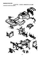
Page 30: ...DEL NUMBER 944 602892 CHASSIS AND ENCLOSURES 74 10 30 219 20 219 23 209 31 1 9 208 209 209 5 5 207 144 26 26 60 26 144 26 10 3 3 3 142 3 3 3 142 208 13 208 11 64 143 60 145 37 37 159 18 14 14 38 38 58 17 29 28 166 39 212 3 2 206 ...

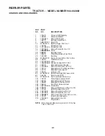
Page 31: ...139976 Bracket Support Fender 37 17490508 Screw Thdrol 5 16 18 X1 2 38 175710 Bracket Asm Pivot Mower Rear 39 174714 Bracket Pivot Laser LT 58 174930 Air Duct P L 60 STD533707 Bolt Rdhd Sqnk 3 8 16unc x 3 4 64 154798 Dash Lower STLT 74 STD541437 Nut Crownlock 3 8 16 Unc 142 175702 Plate Reinforcement STLT 143 154966 Bracket Swaybar Chassis 144 175582 Bracket Pnt Footrest STLT 145 156524 Rod Pivot ...

Page 32: ... 38 61 41 53 35 55 36 62 35 36 22 39 34 16 1 77 77 30 52 56 64 65 212 63 116 70 57 96 26 25 19 24 26 26 76 78 75 74 27 26 15 37 51 89 90 27 51 48 151 202 49 47 50 120 81 156 166 165 82 168 163 14 164 21 8 10 83 159 161 198 158 162 169 150 84 16 199 16 250 71 200 73 16 250 197 95 ...

Page 33: ... Keeper Center Span 61 17120614 Screw 3 8 16 x 875 62 8883R Cover Pedal 63 175410 Pulley Engine 64 71170764 Bolt Hex 65 STD551143 Washer 66 154778 Keeper Belt Engine 70 134683 Keeper Belt Engine 71 169183 Strap Torque Lh Hydro 73 169182 Strap Torque Rh Hydro 74 137057 Spacer Split 75 121749X Washer 25 32 x 1 1 4 x 16 Gauge 76 STD581075 E Ring 77 123583X Key Square 78 121748X Washer 25 32 x 1 5 8 x...

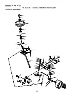
Page 34: ...RACTOR MODEL NUMBER 944 602892 STEERING ASSEMBLY 44 51 54 5 9 5 7 7 9 4 3 32 43 6 43 8 10 40 11 8 6 9 46 46 8 6 9 2 47 47 26 30 28 1 41 42 37 36 37 38 12 39 68 67 67 67 13 65 85 85 68 15 15 15 29 29 82 88 71 17 29 43 91 ...

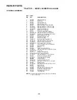
Page 35: ...16 Ga 29 17060612 Screw Thdrol 3 8 16x3 4 30 STD561210 Pin Cotter 1 8 X 3 4 Cad 32 130465 Rod Tie Wire Form 19 75 Mech 36 155099 Bushing Strg 37 152927 Screw 38 139769 Insert Cap Strg Wh Au 39 19183812 Washer 9 16 ID x 2 3 8 OD 12 Ga 40 STD541537 Lock nut 41 100711L Adaptor Wheel Strg 42 145054X428 Boot Steering Shaft 43 121749X Washer 25 32 X 1 1 4 X 16 Ga 44 180640 Extension Steering Shaft 46 12...

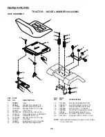
Page 36: ... X 1 X 14 Ga 10 180186 Pan Seat 11 166369 Knob Seaat 1 2 13 Unc Blk 12 121246X Bracket Mounting Switch KEY PART NO NO DESCRIPTION 13 121248X Bushing Snap Blk Nyl 50 Id 14 72050412 Bolt Rdhd Sqnk 1 4 20x1 1 2 15 134300 Spacer Split 28x 96 Yel Zinc 16 121250X Spring Cprsn 1 27 Blk Pnt 17 123976X Nut Lock 1 4 Lge Flg Gr 5 Zinc 21 171852 Bolt Shoulder 5 16 18 Unc 22 STD541431 Nut Hex Lock W Ins 5 16 1...

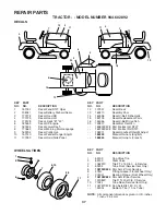
Page 37: ... Diehard Sears 3 177278 Decal Hood RH 4 177279 Decal Hood LH 5 179128 Decal Deck B 42 6 181659 Decal HP Engine 7 181824 Decal Lower Dash 8 170563 Decal Warning Mult Language 9 163204 Decal Craftsman 10 157140 Decal Fender Danger Eng Fr 11 177253 Decal Hood Side Panel KEY PART NO NO DESCRIPTION 6 2 1 5 8 4 10 3 9 11 7 WHEELS TIRES 12 172331 Decal Deck 13 169210 Decal By Pass 14 160396 Decal V Belt ...

Page 38: ...38 REPAIR PARTS TRACTOR MODEL NUMBER 944 602892 ENGINE 2 1 OPTIONAL EQUIPMENT Spark Arrester 29 10 6 5 72 13 26 25 17 3 16 17 81 4 8 23 45 14 38 32 31 34 33 37 33 39 ...

Page 39: ...37 Washer Lock Ext Tooth 3 8 17 17060624 Screw Thdrol 3 8 16x1 1 2 23 169837 Shield BRN DBR Guard 25 145996 Control Choke 26 73920600 Nut Keps 3 8 24 UNF 29 137180 Arrestor Spark 31 157103 Tank Fuel 3 5 STL W O Sensor 32 161696 Cap Fuel Gauge 33 123487X Clamp Hose Blk 34 106082X Strip Foam 37 8543R Line Fuel 38 181654 Plug Drain Oil Easy 39 109227X Pad Spacer 45 17000612 Screw Hex Wsh Thdrol 3 8 1...

Page 40: ...50 45 144 147 147 142 149 142 49 50 51 54 52 53 55 56 34 1 46 44 21 24 25 26 27 2 28 29 23 21 21 21 18 18 20 2 48 59 19 4 3 129 92 131 130 92 5 6 21 40 143 36 40 37 40 159 102 102 104 103 105 106 104 105 106 103 101 114 117 119 116 18 111 118 113 152 151 153 154 157 158 67 153 156 155 113 117 116 118 119 114 18 112 ...

Page 41: ...d Sqn 3 8 16 Unc x 1 3 4 184 19131410 Washer 13 32 x 7 8 x 10 Ga 130794 Mandrel Assembly Includes Hous ing Shaft and Shaft Hardware Only Pulley Not Included 169583 Replacement Mower Complete 1 165892 Mower Deck Assembly 42 2 STD533107 Bolt 3 138017 Bracket Assembly Sway Bar Front 4 165460 Bracket Sway Bar 38 42 Deck 5 STD624008 Retainer Spring 6 178024 Bar Sway Deck 8 850857 Bolt Hex 3 8 24 x 1 25...

Page 42: ...42 REPAIR PARTS TRACTOR MODEL NUMBER 944 602892 MOWER LIFT 15 20 16 1718 20 20 15 20 4 5 6 2 3 1 6 5 4 7 8 12 11 31 32 31 32 19 19 13 13 13 13 ...

Page 43: ... Bearing Nylon Blk 629 ID 7 125631X Grip Handle Fluted 8 122365X Button Plunger 11 139865 Link Lift Lh 12 139866 Link Lift Rh 13 STD624008 Retainer Spring 15 173288 Link Front 16 73350800 Nut Jam Hex 1 2 13 Unc 17 175689 Trunnion 18 73800800 Nut Lock w Wsh 1 2 13 Unc 19 139868 Arm Suspension Rear 20 163552 Spring Retainer 31 169865 Bearing Pvt Lift 32 73540600 Nut Lock 3 8 24 NOTE All component di...

Page 44: ...44 REPAIR PARTS TRACTOR MODEL NUMBER 944 602892 HYDRO GEAR TRANSAXLE MODEL NUMBER 314 0510 ...

Page 45: ...g 54 170406 Bearing Center Block 55 142977 Spring Helical Compression 56 142978 Washer 57 150798 20w 50 Oil 58 170407 Brake Yoke KEY PART NO NO DESCRIPTION 59 170408 Rotor Brake 60 142883 Brake Puck 61 142882 Puck Plate 62 142887 Brake Actuating Pin 63 170410 Hfhcs 1 4 20x2 W Patch SpecialFlange 64 142892 Bolt 1 4 20 X 1 W Patch 65 170411 Spacer 66 170412 Spring Brake Arm Bias 67 170413 Sq Hd Bolt...

Page 46: ...47 865A 447A 865B 447A 1035 1024 943 750 965 523 842 524 287 525 847 45 220 615 219 267 265 216 929A 213 718 1036 EMISSION LABEL 15 89 51A 163 54 212 929 50 617 20 89 552 691 1017 12 4 654 53 188 1058 OWNER S MANUAL 2 710 1280 163 855 304 REPAIR PARTS TRACTOR MODEL NUMBER 944 602892 BRIGGS STRATTON ENGINE MODEL NUMBER 407677 TYPE NUMBER 0229 E1 ...

Page 47: ...4 616 742 552 505 562 209 211 227 40 40 40 36 36 5 5A 34 42 40 33 34 33 42 1023 1023A 51A 231 130 108 633 987 104 137 105 1126 1128 1169 1127 276 276 418 672 95 117 160 1123 150 1124 51 141 125 98 142 947 131 133 975 135 385 601 240 918 628 788 387 121 CARBURETOR OVERHAUL KIT 137 977 CARBURETOR GASKET SET 1124 987 51A 137 105 276 672 1124 104 987 1123 150 276 150 672 51A 1123 117 51 1128 142 633 6...

Page 48: ...YPE NUMBER 0229 E1 358 ENGINE GASKET SET 12 9 51 51A 3 20 7 868 1022 163 691 524 943 276 842 573 405 74 668 1005 363 332 75 1070 1119 334 851 544 802 801 803 310 697 311 797 783 1051 513 797A 1090 309 510 73 23 333 48 726 695 165 1095 VALVE GASKET SET 1022 7 51 163 868 877 474 789 503 579 462 ...

Page 49: ...t Main High Altitude 121 499811 Kit Carburetor Overhaul 125 499804 Carburetor 130 690993 Valve Throttle 131 499805 Kit Throttle Shaft KEY PART NO NO DESCRIPTION 133 499806 Float Carburetor 135 499803 Tube Fuel Transfer 137 690994 Ø Gasket Float Bowl 141 499807 Kit Choke Shaft 142 499808 Ø Nozzle Carburetor 146 690979 Key Timing 150 690995 Ø Gasket Nozzle 160 690996 Retainer Solenoid 163 691001 Gas...

Page 50: ...1011 Adapter Air 865 691012 Cover Air Guide 865A 691014 Cover Air Guide KEY PART NO NO DESCRIPTION 865B 691015 Cover Air Guide 868 690968 Seal Valve 877 393456 Wire Connector Alternator 914 691127 Screw Rocker Cover 918 694000 Hose Vacuum 929 695239 Screw Choke Control Bracket 929A 691003 Screw Choke Control Bracket 943 690589 Seal O Ring Oil Pump Cover 947 499809 Solenoid Fuel 965 499613 Cover Oi...

Page 51: ... never across the face Do not mow slopes greater than 15 degrees Make turns gradually to prevent tipping or loss of control Exercise extreme caution when changing direction on slopes 1 Fold this page along dotted line indicated above 2 Hold page before you so that its left edge is vertically parallel to a tree trunk or other upright structure 3 Sight across the fold in the direction of hill slope ...

Page 52: ...PRINTED IN U S A 186333 12 02 02 RH ...

Reviews: