background image

OPERATOR’S MANUAL

14

SECTION 1

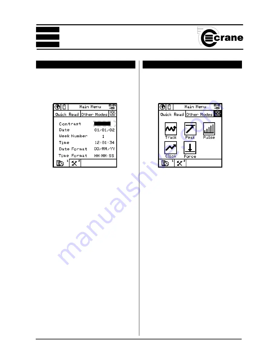
 SELECTING THE QUICK READ MODE

From the Main Menu select Quick Read.  The available

modes are:-  Track,  Peak,  Pulse, Click or Force.

NOTE:

   Before entering the Quick Read Mode, make sure

a suitable transducer is connected to the TorqueStar Opta,

otherwise an error message will be displayed on the screen.

Attach the cable from the transducer to the 25-way D

connector on the back of the TorqueStar.

The selected Quick Read Mode screen will now appear. If

the transducer connected is not a UTA, the transducer

settings must be specified before readings can be taken. In

this case, the screen for the transducer settings, will be

displayed automatically  (see Changing the Settings

page 16).

If a UTA transducer is connected, the Opta will automatically

recognise the settings.

 SETTING THE TIME AND DATE

From the Main Menu,  enter the Time and Date setup screen

- see below. The screen displays the currently set date, week

number, time and the date and time format.

To change Screen Contrast:

Select Contrast.  Adjust contrast using left and right arrow

keys.

To change the date:

Select the date.  The Date is displayed in editable fields.

Enter the required figures using the numbers on the key-

pad.  When date is correct, ENTER to return to the setup

screen.

To change the time:

Select the time.  The time is displayed in editable fields.

Enter the required figures using the numbers on the keypad.

When the time is correct,  ENTER to return to the setup

screen.

To change the date format:

Select the date format. Highlight the required option and

ENTER to return to the setup menu.

To change the time format:

Select the time format. Highlight the required option  and

ENTER to return to the setup menu.

Summary of Contents for DTT Opta

Page 1: ...NOTICE ALL RIGHTS RESERVED Reproduction of any part of this manual in any form whatsoever without the prior permission in writing from Crane Electronics Ltd is forbidden Copyright March 2012 by Crane Electronics Ltd The contents of this manual are subject to change without prior notice ...

Page 2: ...e TorqueStar Opta and the DTT Opta As they share similar software and many features are common to both devices the manual is split into 2 sections The 1st main section covers the operating instructions for the TorqueStar Opta and the 2nd section covers only areas where the operation of the two devices differs This includes the integral printer of the DTT Opta and its interchangeable transducer mod...

Page 3: ...r 15 Taking a Reading Quick Read 15 Changing the Settings Quick Read 16 Plot Trace Last Reading only 16 Quick Store Mode 17 Taking a Reading Quick Store 18 Changing the Settings Quick Store 19 View Readings Quick Store 20 View Statistics 21 Plot Readings 21 Jobs 21 View Readings Jobs 22 Adding New Jobs to List 23 Rounds 24 Adding New Rounds to List 25 Transducer Templates 25 Using a Bar Code Reade...

Page 4: ...arge for normal use When the mains adaptor is plugged into the socket and switched on at the mains the red LED will come on to indicate the Opta is charging correctly Optional Fast Charge Opta TorqueStar Optas with optional Fast Charge are supplied with internal NiMH Nickel Metal Hydride batteries From fully discharged the unit will require a charging period of only 2 5 hours approx Opta models ha...

Page 5: ...rocess while the simple alphanumeric keypad enables fast data entry when required Light enough for carrying on a neckstrap yet robust to withstand the rigours of the factory environment TorqueStar Opta also sports integrated rubber bumpers to protect finished product from accidental damage The TorqueStar Opta supports the following features Multiple languages Track peak 1st peak click and pulse me...

Page 6: ...ins powered needs optional charger WEIGHT Standard Charge 1 480Kg Fast Charge 1 355Kg CONSTRUCTION Ruggedised injection moulding with rubberised bumpers OUTPUT Serial RS 232 Data DIMENSIONS 255mm L x 166mm W x 152mm H SECTION 1 250mm 255mm O A approx 166mm O A 145mm 50mm 152mm O A ...

Page 7: ...e in 14 steps from 75Hz to 6144Hz Calibration Issued with calibration certificate traceable to national and international standards 12 months typical recalibration interval Warranty 12 months parts and labour Servicing Crane Electronics Ltd offer a full repair facility and calibration to UKAS and international standards MAINS ADAPTOR POWER REQUIREMENTS Standard Charge Input 230V AC 50 Hz 300mA UK ...

Page 8: ...OPERATOR S MANUAL 8 CONTROLS AND CONNECTIONS STATUS LED CHARGER CONNECTED LED CHARGING FAULT LED FAST CHARGER ONLY REAR OF UNIT SCREEN SECTION 1 ...

Page 9: ...the keys work as a mobile phone keypad Press the key a number of times until the correct character is displayed I E to type the letter C press key 23 times Screen TASK BAR Items here are numbered Press the equivalent number on the keypad to select Main display area for torque readings Information varies according to the mode selected Menu icons also displayed here Mode selected displayed here Dire...

Page 10: ... Torquestar Opta using the optional PC connection cable CBL 757 0 0 0 0 and Serial Printer Adapter CBL 758 01CR 0 0 Attach one end of the cable to the Torquestar Opta 9 way connector as shown The 25 way end of the Serial Printer Adapter connects to the 25 way Serial connector on the Printer The printer should be configured to the following settings Baud Rate 9600 8 Data Bits Stop Bit 1 No Parity F...

Page 11: ...klight off Select required Options Return to the Power Menu Return to the Main Menu COLD RESET CAUTION THIS FEATURE WILL RESTORE THE OPTA TO ITS INITIAL FACTORY SETTING USE THIS FEATURE WITH CARE AS ALL SETTINGS AND DATA WILL BE LOST To perform a Cold Reset From the Main Menu access the Tools screen Select the Reset icon The following message will appear on the screen ATTENTION ALL DATA SETTINGS A...

Page 12: ...now be operating in the chosen language TO ACCESS OTHER MODES Select the Other Modes Panel Select the required Icon The Options are Quick Store see page 17 Jobs see page 21 Scan Setup see page 27 Rounds see page 24 TOOLS MENU The Tools Menu gives the user access to the following features USERS See page 13 UNLOCK See page 28 TXDS transducer templates See page 25 RESET Cold reset See page 11 COMMS C...

Page 13: ...ed by keying in the amended details as for new users Users can be deleted by selecting the Erase User Icon The screen will then prompt delete user Press ENTER to Confirm NOTE Only when there are no users or the first user on the list is logged in can changes be made to the user list A user must be logged in to record data against Jobs or use the Scan Setup mode LOGGING IN Select the icon The scree...

Page 14: ...ta will automatically recognise the settings SETTING THE TIME AND DATE From the Main Menu enter the Time and Date setup screen see below The screen displays the currently set date week number time and the date and time format To change Screen Contrast Select Contrast Adjust contrast using left and right arrow keys To change the date Select the date The Date is displayed in editable fields Enter th...

Page 15: ... a Pulse Mode screen The display will show the amount of torque applied in the chosen Units of Measure Nm shown here the type of transducer and the serial number The information on the screen will vary according to the type of Measure mode selected The top of the screen shows the mode selected as an icon The direction of the applied torque is shown if applicable and the number of pulses if in Puls...

Page 16: ...arameter choose between Angle and None and ENTER To change the Angle Threshold key in the required figure between the max and min displayed on screen and ENTER CHANGING THE SETTINGS QUICK READ To change the settings for the chosen Quick Read mode select the Settings icon The screen will now display the Settings Menu and the user can change some or all the following Transducer settings for non UTA ...

Page 17: ...ss other modes select the Other Modes panel A new screen appears Select the Quick Store icon Highlight the Quick Store icon and select The available modes are Peak Pulse or Click NOTE Before entering the QUICK STORE Mode make sure a suitable transducer is connected to the TorqueStar Icons used in Plot Screen Fine movement of cursor zoom box Toggle Coarse movement of cursor zoom box Print graph Zoo...

Page 18: ... the status of the reading AMBER Measurement is below the preset minimum torque setting An arrow pointing down will appear on the screen to confirm and the machine will give a single beep GREEN Measurement is OK within the specified torque range and the machine will give 2 beeps RED Measurement is above the preset maximum setting An arrow pointing up will appear in the display and the machine will...

Page 19: ...ter LSL The options available will vary according to the chosen measure mode To change the Units of Measurement highlight the required Units from the list and ENTER To change the Direction of rotation highlight the required Direction Right Left or Auto and ENTER To change the Cycle End Time highlight the required figure from the list and ENTER To change the Frequency Response highlight the require...

Page 20: ...ram USL and LSL can be displayed as either an angle or as a percentage of the USL To change highlight the desired option radio button and ENTER To change the 2nd Param Target key in the required figure VIEW READINGS QUICK STORE From the Quick Store mode select View readings A list of the current readings will appear in a similar format to the one shown below View Readings Torque Angle Nm 001 10 05...

Page 21: ... Plot the Readings The Plot Readings screen will appear showing the plot and the Upper and lower limits Scroll the plot to the right to view any points not able to fit on to the screen or Scroll to the left Select Icon to toggle between Torque and Second Parameter if selected JOBS NOTE A user must be logged in before any Job can be performed The TorqueStar Opta can store a number of jobs consistin...

Page 22: ...n including or excluding any readings marked for faults as described Show a plot for the readings See page 21 VIEW READINGS JOBS From Jobs mode select View Readings A list of the current readings will appear in a similar format to the one shown in Quick Store with the addition of the Subgroup number the date and time the transducer serial number and the Job name Scroll down the readings to access ...

Page 23: ...SL The Job setup parameters are stored over several pages To access these move to the next page or move to the previous page Altering these parameters is similar to the setup in the Quick Store Mode To edit the number of samples to be taken select Samples and key in the required figure between the minimum and maximum shown on screen To edit the number of subgroups to be taken select Samples and ke...

Page 24: ...nother round to perform or return to the Other Modes Menu To change the Torque LSL Lower Specification Limit key in the required figure between the max and min displayed on screen To change the 2nd Parameter choose between Angle Pulse and None To change the Angle Threshold key in the required figure between the max and min displayed on screen To change the 2nd Param USL Upper Specification Limit k...

Page 25: ... Edit Round Delete Round TRANSDUCER TEMPLATES The TorqueStar Opta has 9 preset transducer templates which are editable by the user This can be selected by the user in Jobs mode if the transducer is non UTAand therefore not recognised by the Opta Select the Sampling field Select the required sampling option from the list Options are In any order Vertical Horizontal Vert plus prompt Horiz plus promp...

Page 26: ...emplates screen without change CANCEL To change the Millivolts Volts key in the required figure between the max and min displayed on screen To return to the Txd Templates screen without change CANCEL To change the Bridge Resistance key in the required figure between the max and min displayed on screen To return to the Txd Templates screen without change CANCEL The figure to the right of the Transd...

Page 27: ...e rear of the Opta NOTE for additional information please refer to the documentation which came with your scanner Before First Use The scanner must be setup by scanning the three codes on page 28 Certain text fields on the TorqueStar Opta will allow the input of barcode data We recommend the data is only scanned once and the green ENTER key is pressed to verify the data is correct Jobs Mode Barcod...

Page 28: ...OPERATOR S MANUAL 28 SECTION 1 BAR CODE READER INITIAL SETUP These bar codes must be scanned in this order to initialise the reader before first use SET DISABLE LABEL I D CONTROL END ...

Page 29: ...ain menu select the Tools menu Select the Unlock icon The activation code will appear on the screen with an arrow below the first digit The display will now show the communications screen For Information on using Opta Comms software see the Opta Comms Manual COMMUNICATIONS The Opta can be connected to a Windows based PC to upload and download data using the Opta Comms software available from Crane...

Page 30: ...ay be encountered during operating the Opta as greyed out items When attempts are made to access these icons an alert message will appear advising the user that this item is currently unavailable It is possible for the user to upgrade to include these options by contacting Crane Electronics Ltd An update activation code can be supplied to enable the user to access these features without the need t...

Page 31: ...es the following formula Max Min x Cam Factor 6 x Average Sample Value CAM Factor is taken from a table in the case of 5 x 6 samples 1 910 High Output Torque transducer with no coding links but internal pre amplifierTransducer H O giving an output signal level of typically 1 or 2 volts Horizontal Collection of data by round taking one reading for each sampling Job in turn Industry Standard Transdu...

Page 32: ...t is possible with TorqueStar Opta to read a transducer calibrated in say Nm and convert internally to display and store in any of the other torque units UTA Tx Family of torque transducers which TorqueStar Opta can identify by coding links UTA Tx ID Specification of transducer by rating in preselected units Used as an identity or name Vertical Collection of data by round where a full sub group is...

Page 33: ...roduct family users familiar with TorqueStar Opta will already know how to use DTT Opta and vice versa PACKING LIST The following items are supplied with the DTT Opta unit 1 x DTT Opta 1 x Transducer 1 x User Manual this book 1 x Quick start guide 1 x Mains adaptor charger 1 x Menu Navigation Guide Please check these items are all present and notify Crane immediately of any shortages CARE STORAGE ...

Page 34: ... and printer Transducer Module 1 3 Kg Printer Module 0 22 Kg DIMENSIONS Overall 255mm L x 255mm W x 79mm H Transducer 105 mm L x 85 mm W x 79 mm H Bottle top or adjustable component fixture 10 130 mm max gripping dimensions SPECIFICATIONS MAINS ADAPTOR POWER REQUIREMENTS Input 230v AC 50HZ 700mA UK and Euro models Input 115v AC 60HZ 700mA US models SECTION 2 ...

Page 35: ...ABLE TRANSDUCER MODULE VERTICAL JOINT KIT OPTIONAL STATUS LED CHARGER CONNECTED LED CONNECTOR FOR MAINS CHARGER 9 WAY CONNECTOR FOR PC PRINTER CABLE CONNECTORS FOR TRANSDUCER MODULE REAR OF UNIT SCREEN INTERCHANGEABLE TRANSDUCER MODULE HORIZONTAL FIXING HOLES FIXING HOLES TRANSDUCER BOLT FIXING HOLES SECTION 2 ...

Page 36: ...harge state the batteries will fully discharge in 25 50 days To prevent the loss of all setup data the unit has additional battery backup for the internal memory PRINTING Printing The DTT Opta can be set to automatically send its readout data to a serial printer or the unit s optional integral printer Press 3 to toggle between Integral printer and external printer Press 4 to toggle between the 2 d...

Page 37: ...UCER MODULE FITTING THE JOINT KIT Ensure joint kit is located fully into Square Drive on the Transducer Module FITTING THE BOTTLE TOP OR ADJUSTABLE COMPONENT FIXTURE Ensure bottle top fixture is located fully into Square Drive on the Transducer Module ...

Page 38: ...sible to clamp a bottle or container from 10mm to 130mm in diameter Ensure that the white pegs are properly seated in the slots so that they cannot rotate when the bottle closure is turned MEASURING THE TORQUE Select the desired operating mode from Section 1 Tighten or release the closure as required to obtain readings MOUNTING THE UNIT The DTT Opta is designed for optional wall mounting as shown ...

Page 39: ...Remove this page to use as a template for the fixing holes ...

Reviews: