background image

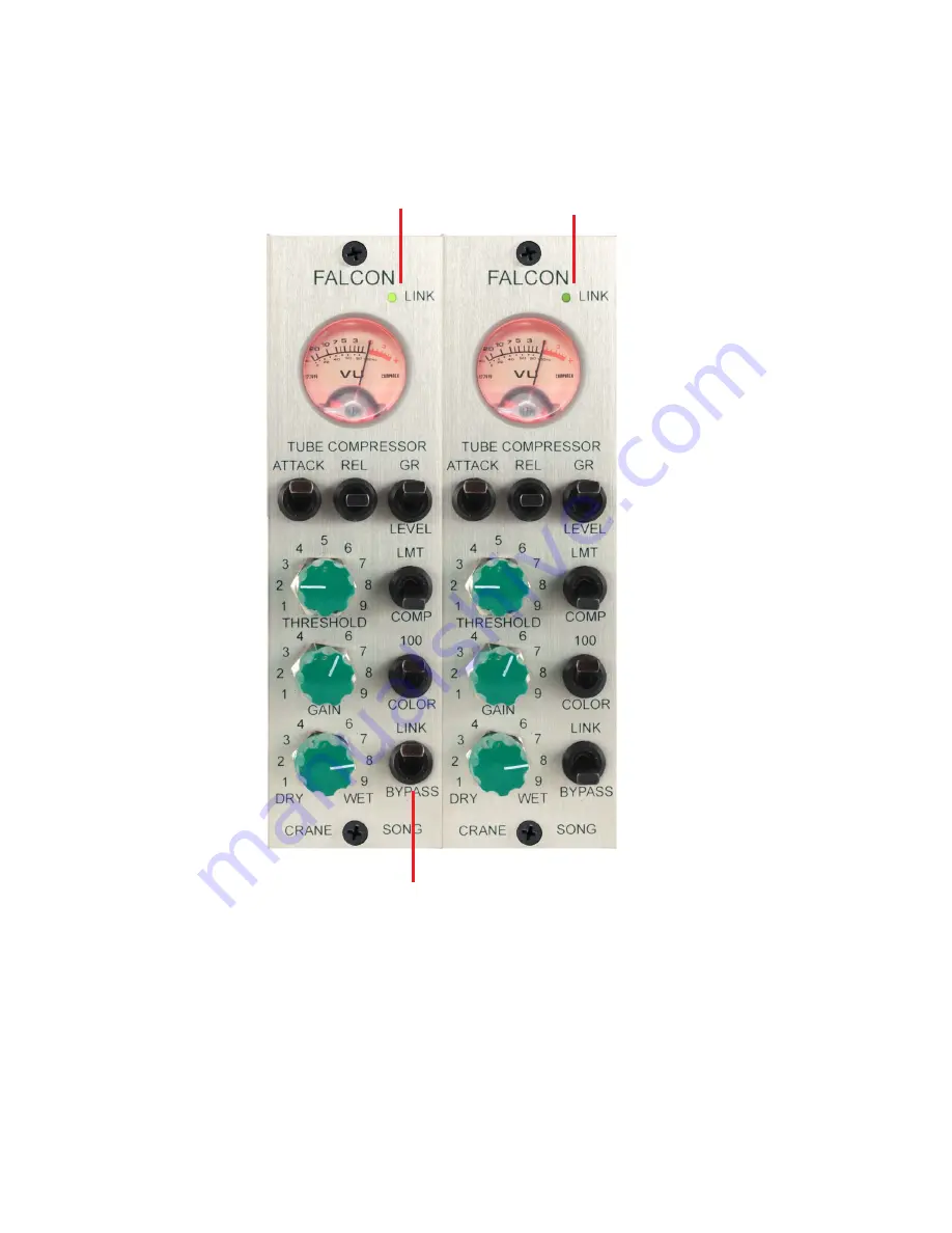
This channel is the MASTER

Set to
BYPASS

Set to
LINK

This channel is the SLAVE

Bright LED indicates the
MASTER

Dim LED indicates the
SLAVE

LINK MODE OPERATION

The GAIN and DRY-WET controls operate 

individually

, all others are

controlled by the MASTER.  The SLAVE channel must first be in BYPASS
for the LINK to work

Summary of Contents for Falcon

Page 1: ...East 5th Street Superior WI 54880 USA tel 715 398 3627 fax 715 398 3279 www cranesong com OPERATOR S MANUAL Version 1 0 20160917 2013 Crane Song LTD Subject to change without notice Printed in the U S A 1 FALCON ...

Page 2: ...will be a cleaner more accurate sound where ae the 100 position is more color WET DRY This is the mix between the original signal and the processed audio When in link mode the WET DRY controls operate independently BYPASS SWITCH This is a three position switch In the bypass position the bottom position Falcon is removed from the audio path In the IN position The middle position Falcon is switched ...

Page 3: ...d THRESHOLD controls are controlled on the master channel THRESHOLD The threshold control governs the amount of gain reduction GAIN The gain control will adjust the compressor gain from off to 15 dB of gain When linked the gain controls operate independently ...

Page 4: ...ATTACK an RELEASE have 3 positions Meter switch compressor limiter mode system color Link In Bypass ...

Page 5: ...is channel is the SLAVE Bright LED indicates the MASTER Dim LED indicates the SLAVE LINK MODE OPERATION The GAIN and DRY WET controls operate individually all others are controlled by the MASTER The SLAVE channel must first be in BYPASS for the LINK to work ...

Page 6: ...lcon is a feedback design as a result the ratio changes depending on how much gain reduction is taking place This measurement was made with the Attack set to fast Release set to mid The threshold was set so that with a 24dbu input there is16 db of gain reduction taking place on the graph ...

Page 7: ...LINK CABLE CONNECTION ...

Page 8: ...pecified signal level is 26 dbu Noise Floor 82 5 dbu measured 20Hz to 20 kHz Power 110mA with 16 volt bipolar power supplies Tube 12AX7B Attack Time For a 12 db change 100uS 7mS 20mS Release Time For a 12 db change 75mS to 200mS 300mS to 1S 1 4S to 3 5S the release time changes depending on the signal SPECIFICATIONS ...

Reviews: