background image

8

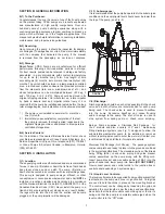
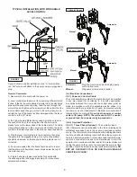
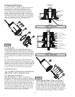
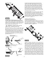
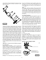
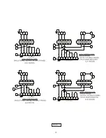
Figure 2 shows a typical installation of an “A” version float, 

(an “AU” version will attach to the pump), using a piggy-back 

plug.

General Comments: 

1) Never work in the sump with the power on.

2) Level controls are factory set for a pumping differential of 9 

inches. If that is the cycle desired, simply circle the discharge 

pipe with the pipe mounting strap, feed the end through the 

worm drive, and tighten with a screwdriver. Be certain that the 

level control cannot hang up or foul in it’s swing. Also, make 

certain the top of the pump is still submerged when the level 

control is in the ‘off’ mode.

3) If a higher pump differential is needed, grip the cord near 

the neck of the float, then using the other hand, exert a 

steady force on the lower edge of the cable clamp. The cable 

clamp should slide up to the new pivot point. Attach the level 

control to the discharge hose in the manner described above.

4) Plug the level control plug into the receptacle, then plug 

the pump into the piggyback plug. One cycle of operation 

should be observed, so that any potential problems can be 

corrected.

5) It is recommended that the float should be set to insure 

that the sump well liquid level never drops below the top of 

the motor housing.

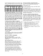
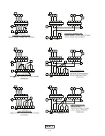
6.) Figure 3 shows a typical connection for pumps with 

the wide angle float and piggy-back plug. For manual and 

automatic operations.

Automatic - 


Plug float cord into outlet, then plug pump


cord into float cord.

Manual - 


Plug pump cord directly int outlet.

C-4) Electrical Connections:

C-4.1) Power and Control Cable:

The cord assembly mounted to the pump must not be modified 

in  any  way  except  for  shortening  to  a  specific  application. 

Any splice between the pump and the control panel must be 

made in accordance with all applicable electric codes. It is 

recommended that a junction box, if used, be mounted outside 

the sump or be of at least Nema 4 (EEMAC-4) construction if 

located within the wet well. 

Do not use the power or control 

cable to lift pump. NOTE: The white wire is NOT a neutral 

or ground lead, but a power carrying conductor.

C-4.2) Overload Protection :

C-4.2-1)  Three Phase (Optional) - 

The normally closed 

(N/C) thermal sensor is embedded in the motor windings and 

will detect excessive heat in the event an overload condition 

occurs. The thermal sensor will trip when the windings become 

too hot and will automatically reset itself when the pump motor 

cools to a safe temperature. It is recommended that the thermal 

sensor be connected in series to an alarm device to alert the 

operator of an overload condition, and/or the motor starter coil 

to stop the pump. In the event of an overload, the source of this 

condition should be determined and rectified immediately. 

DO 

NOT LET THE PUMP CYCLE OR RUN IF AN OVERLOAD 

CONDITION OCCURS !

120 Volt 1 Phase

Automatic

240 Volt 1 Phase

FIGURE 3

Manual

Manual

Automatic

TYPICAL INSTALLATION WITH WIDE ANGLE 

LEVEL CONTROL

FIGURE 2

Summary of Contents for 104872

Page 1: ...ement program product changes may occur As such Crane Pumps Systems reserves the right to change product without prior written notification 420 Third Street 83 West Drive Bramton Piqua Ohio 45356 Ontario Canada L6T 2J6 Phone 937 778 8947 Phone 905 457 6223 Fax 937 773 7157 Fax 905 457 2650 www cranepumps com Form No 105240 Rev AK Series SE 3SE L DS 5 75 1 HP 1750RPM 60 Hz Single and Double Seal St...

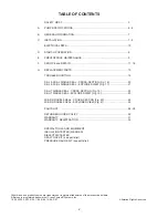
Page 2: ...g 18 22 SE HT SINGLE SEAL EXPLODED VIEW Fig 19 23 3SE DS DOUBLE SEAL CROSS SECTION Fig 20 24 3SE DS DOUBLE SEAL EXPLODED VIEW Fig 21 25 PARTS LIST 26 28 RETURNED GOODS POLICY 32 WARRANTY 31 WARRANTY REGISTRATION 32 SPECIAL TOOLS AND EQUIPMENT INSULATION TESTER MEGGER DIELECTRIC TESTER SEAL TOOL KIT see parts list PRESSURE GAUGE KIT see parts list Other brand and product names are trademarks or reg...

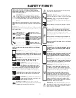
Page 3: ...ert fingers in pump with power connected Always wear eye protection when working on pumps Make sure lifting handles are securely fastened each time before lifting DO NOT operate pump without safety devices in place Always replace safety devices that have been removed during service or repair Secure the pump in its operating position so it can not tip over fall or slide DO NOT exceed manufacturers ...

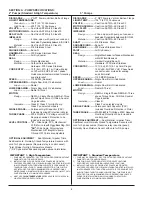
Page 4: ...00 Series Stainless Steel PAINT Air Dry Enamel SEAL Design Single Mechanical or Tandem Mechanical with Oil Filled Reservoir Material Carbon Ceramic Buna N Hardware 300 Series Stainless CORD ENTRY 15 ft 5 m 20 ft 6 1 m Cord Plug on 120 Volt 5HP 240 Volt 1 Phase Quick connect custom molded for sealing and strain relief SPEED 1750 RPM Nominal UPPER BEARING Single Row Ball Oil lubricated Load Radial L...

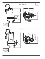
Page 5: ...gle Seal SE A SE HTA Single Seal SE AU SE HTAU Single Seal Plugs for 120 Volt and 5Hp 240 Volt Single Phase Models Plugs for 120 Volt and 5Hp 240 Volt Single Phase Models Plugs for 120 Volt and 5Hp 240 Volt Single Phase Models ...

Page 6: ...6 Plugs for 120 Volt and 5Hp 240 Volt Single Phase Models inches mm Plugs for 120 Volt and 5Hp 240 Volt Single Phase Models 3SE L Single Seal 3SE DS Double Seal ...

Page 7: ...n or basin that is free of hard debris like gravel stones sand or earth The sump lift station or basin shall be vented in accordance with local plumbing codes This pump is designed to pump sewage effluent or other nonexplosive or noncorrosive wastewater and shall NOT be installed in locations classified as hazardous in accordance with the National Electrical Code NEC ANSI NFPA 70 or the Canadian E...

Page 8: ...erations Automatic Plug float cord into outlet then plug pump cord into float cord Manual Plug pump cord directly int outlet C 4 Electrical Connections C 4 1 Power and Control Cable The cord assembly mounted to the pump must not be modified in any way except for shortening to a specific application Any splice between the pump and the control panel must be made in accordance with all applicable ele...

Page 9: ...amped on the pump identification plate to the available power D 2 Check Pump Rotation Before putting pump into service for the first time the motor rotation must be checked Improper motor rotation can result in poor pump performance and can damage the motor and or pump To check the rotation suspend the pump freely momentarily apply power and observe the kickback Kickback should always be in a coun...

Page 10: ... 5 3 14 4 SOW 0 570 14 5 40 80 52 00 3SE554L 0 5 600 3 60 1750 H B 1 0 3 4 14 4 SOW 0 570 14 5 77 60 89 76 3SE774L 0 75 200 240 1 60 1750 G K F 7 4 7 0 21 5 25 8 14 3 SOW 0 530 13 5 1 86 10 20 2 74 10 56 3SE794L 0 75 200 240 3 60 1750 H K F 4 8 4 5 13 7 15 4 14 4 SOW 0 570 14 5 5 49 6 28 3SE744L 0 75 480 3 60 1750 K F 2 2 7 7 14 4 SOW 0 570 14 5 21 96 24 51 3SE754L 0 75 600 3 60 1750 L B 1 5 7 2 1...

Page 11: ...the pressure does not hold then the leak must be located and repaired Pumps that have NOT had the oil drained from the Motor Housing The pressure test may be done with the oil at its normal level Remove pipe plug 39 from motor housing 6 Apply pipe sealant to pressure gauge assembly and tighten into hole see Figure 4 Pressurize motor housing to 10 P S I Use soap solution around the sealed areas abo...

Page 12: ...n volute 1 Position lockwasher 12 on cap screw 26 and screw into volute 1 Torque to 100 in lbs Check for free rotation of motor and impeller F 3 Shaft Seal Service CAUTION Handle seal parts with extreme care DO NOT scratch or mar lapped surfaces F 3 1 Disassembly and Inspection Outer Seal All Units To expose shaft seal 28 for examination disassemble volute and impeller as outlined in paragraph F 2...

Page 13: ...rotating member 28b onto stationary member using seal pusher as described above Place spring 28c and retaining ring 28d onto rotating member 28b Assemble impeller and volute as outlined in paragraph F 2 2 Replace oil as outlined in paragraph F 1 4 F 4 Motor and Bearing Service F 4 1 Disassembly and Inspection To examine or replace the motor 7 capacitor 9 single phase units controls 55 56 optional ...

Page 14: ...bearing 25 on the motor shaft position squarely onto the shaft applying force to the inner race of the bearing only until bearing seats against the retaining ring 24 Included with motor Motor Slide lower bearing 25 and motor shaft squarely into the seal plate 5 until bearing seats on the bottom Place stator over rotor lining up motor bolts with holes in seal plate 5 Position capacitor 9 single pha...

Page 15: ...onfiguration This number is used for ordering and obtaining information G 3 MODEL NUMBER This designation consists of numbers and letters which represent the discharge size series horsepower motor phase and voltage speed and pump design This number is used for ordering and obtaining information G 4 SERIAL NUMBER The serial number block will consist of a six digit number which is specific to each p...

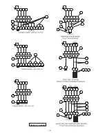
Page 16: ...16 FIGURE 13 ...

Page 17: ...17 FIGURE 13 ...

Page 18: ...18 FIGURE 13 CONTIUED ...

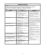
Page 19: ...k cutter for freedom of operation security and condition Clean cutter and inlet of any obstruction 9 Loosen union slightly to allow trapped air to escape Verify that turn off level of switch is set so that the suction is always flooded Clean vent hole 10 Remove examine for damage Replace pump stator if required 11 Repair fixtures as required to eliminate leakage 12 Check pump temperature limits fl...

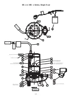
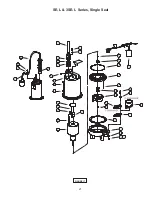
Page 20: ...20 FIGURE 16 SE L 3SE L Series Single Seal ...

Page 21: ...21 FIGURE 17 SE L 3SE L Series Single Seal ...

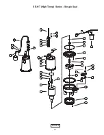
Page 22: ...22 FIGURE 18 SE HT High Temp Series Single Seal ...

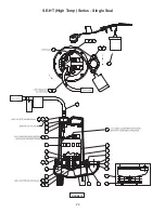
Page 23: ...23 FIGURE 19 SE HT High Temp Series Single Seal ...

Page 24: ...24 FIGURE 20 3SE DS Series Double Seal ...

Page 25: ...25 FIGURE 21 3SE DS Series Double Seal ...

Page 26: ...4L SE1074L 3SE1074L 029792BD 070963 3SE774DS 3SE1074DS 071354BS None SE794L SE744L 3SE794L 3SE744L SE1094L None SE1044L 3SE1094L 3SE1044L 071354BD None 3SE794DS 3SE744DS 3SE1094DS 3SE1044DS 092855BS None SE754L 3SE754L SE1054L 3SE1054L 092855BD None 3SE754DS 3SE1054DS 8 96 oz 029034 Oil All single seal 120oz 029034 Oil All double seal Includes 24 oz in Seal Chamber 9 1 034964 Capacitor 30MFD 1 Pha...

Page 27: ...a 084346TL 4 63 Dia 084346TM 4 50 Dia 084346TN 4 38 Dia 084346TP 4 25 Dia 084346TQ 4 13 Dia 084346TR 4 00 Dia 36 1 027344 Gasket 39 1 014270 Pipe Plug 375 NPT 40 2 1 36 1 Hex Hd Cap Screw 2 Discharge 3 8 16 x 1 25 Lg Stainless 2 23030 59 Hex Hd Cap Screw 3 Discharge 5 16 18 x 1 50 Lg Stainless 41 A R Loctite 242 42 A R Permatex 2C 43 2 082727 Washer 2 Discharge 3 8 Stainless 44 1 003217 Pipe Plug ...

Page 28: ... Temp plug included ITEM 16 120 VOLT 1 PHASE High Temp plug included ITEM 16 240 VOLT 1 PHASE 0 5HP STD HT plug included ITEM 16 240 VOLT 1 PHASE 0 75 1HP STD HT no plug ITEM 16 3 PHASE no plug ITEM 55 OPTIONAL STD Temp Piggy Back Float Switch A Series ITEM 55 OPTIONAL High Temp Piggy Back Float Switch A Series ITEM 56 OPTIONAL Temperature 3 Phase ITEM 56 OPTIONAL Moisture and Temperature Sensor 3...

Page 29: ...29 Notes ...

Page 30: ...30 Notes ...

Page 31: ...es between the results of field testing conducted by or for user and laboratory tests corrected for field performance the latter shall control RECOMMENDATIONS FOR SPECIAL APPLICATIONS OR THOSE RESULTING FROM SYSTEMS ANALYSES AND EVALUATIONS WE CONDUCT WILL BE BASED ON OUR BEST AVAILABLE EXPERIENCE AND PUBLISHED INDUSTRY INFORMATION SUCH RECOMMENDATIONS DO NOT CONSTITUTE A WARRANTY OF SATISFACTORY PE...

Page 32: ...d Or Decontaminated As Necessary Prior To Shipment To Insure That Employees Will Not Be Exposed To Health Hazards In Handling Said Material All Applicable Laws And Regulations Shall Apply IMPORTANT WARRANTY REGISTRATION Your product is covered by the enclosed Warranty If you have a claim under the provision of the warranty contact your local Crane Pumps Systems Inc Distributor ...

Reviews: