background image

21

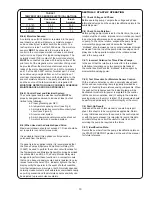
E-2.2) Reassembly:


To install impeller (6), apply a thin film of oil to motor shaft 

and slide impeller straight onto shaft, keeping keyways 

lined up. Drive key (7) into keyway. Thread cap screw (8) 

and washer (8A) into shaft and torque to 45 ft. lbs. Rotate 

impeller to check for binding. Place o-ring (9) on seal plate 

pilot diameter lining up holes and install impeller and motor 

assembly onto volute (10). Loctite cap screws (2), insert 

into volute and motor assembly and torque to 35 ft. lbs. 

Check for free rotation of motor and impeller. 

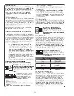
E-3)  Outer  Shaft Seal  Service:

CAUTION ! - Handle seal parts with extreme care.  

DO NOT scratch or mar lapped surfaces.

E-3.1) Disassembly and Inspection:


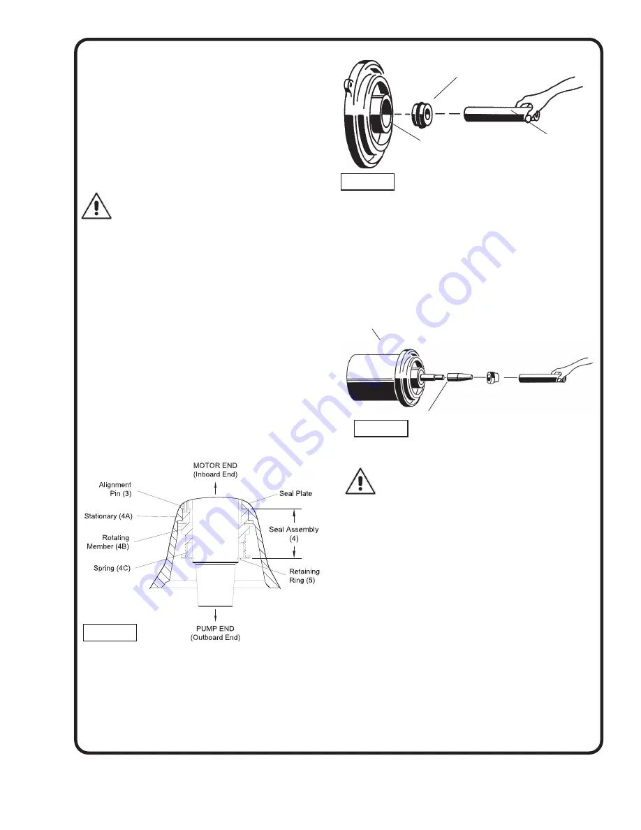
To expose outer shaft seal (4) for examination, remove 

Impeller and Volute per Section E-2.1. Set motor assembly 

(1) in the inverted position to prevent loss of oil. Remove 

snap ring from motor shaft, then retaining ring (5), spring 

(4C) and rotating member (4B) from shaft, See Figure 

6. Examine all seal parts and especially contact faces. 

Inspect seal for signs of wear such as uneven wear pattern 

on stationary members, chips and scratches on either seal 

face. 

DO NOT

 interchange seal components, replace the 

entire shaft seal (4). If replacing seal, remove stationary 

(4A) from mounting plate by prying out with flat screw 

driver. 

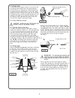
E-3.2) Reassembly:


Lightly oil 

(DO NOT use grease)

 outer surface of stationary 

member (4A). Press stationary member (4A) firmly into 

mounting plate using a seal pusher aligning seal with pin, 

nothing but the seal pusher is to come in contact with seal 

face (See Fig. 7). 

Make sure the stationary member is in straight and that 

the rubber ring is not out of it’s groove. Lightly oil 

(DO NOT 

use grease)

 shaft and inner surface of bellows on rotating 

member (4B) see Figure 8. With lapped surface of rotating 

member (4B) facing inward toward stationary member (4A), 

slide rotating member (4B) onto shaft using a seal pusher, 

until lapped faces of (4A) and (4B) are together.  


(See Fig. 8).

IMPORTANT ! - It is extremely important to keep 

seal faces clean during assembly. dirt particles 

lodged between these faces will cause the seal 

to leak.

Place spring (4C) over shaft and in place on rotating 

member (4B), making sure it is seated on retainer and not 

cocked or resting on bellows tail. Slide retaining ring (5) 

over shaft and let rest on spring (4C). Replace snap ring 

onto motor shaft. Inspect gasket (9) and replace if cut or 

damaged. Assemble impeller and volute as outlined in 

paragraph E-2.2.

FIGURE 6

Stationary Member (4A) Pol-

ished Face Out

Motor Mounting Plate 

Seal Pusher

FIGURE 7

Rotating Member (4B)

Bullet

Motor

Seal Pusher

Stationary

FIGURE 5

Summary of Contents for BARNES 10XSHD

Page 1: ...AH 28 Frame Explosion Proof Class 1 Division 1 Groups C D T4 3XSHV Vortex Pumps 20 40HP 3450RPM 4XSHV Vortex Pumps 20 50HP 3450RPM 4XSHM Monovane Pumps 20 60HP 1750RPM 20 30HP 1150RPM 4XSHD Dual Vane Pumps 20 60HP 1750RPM 20 40HP 1150RPM 6XSHV Vortex Pumps 20 60HP 1750RPM 20 40HP 1150RPM 10 30HP 870RPM 6XSHM Monovane Pumps 20 60HP 1750RPM 20 25HP 1150RPM 6XSHD Dual Vane Pumps 20 60HP 1750RPM 20 40...

Page 2: ...Fig 11 12 Before March 2016 26 PARTS LISTS Before March 2016 27 XSH CROSS SECTIONS Fig 13 14 After March 2016 28 EXPLODED VIEW Fig 15 16 After March 2016 29 PARTS LISTS After March 2016 30 PARTS LISTS CONTINUED 30 47 WARRANTY 49 RETURNED GOODS POLICY 50 WARRANTY REGISTRATION 50 START UP REPORT 51 52 Other brand and product names are trademarks or registered trademarks of their respective holders B...

Page 3: ...ear loose clothing that may become entangled in the impeller or other moving parts WARNING Keep clear of suction and discharge openings DO NOT insert fingers in pump with power connected Always wear eye protection when working on pumps Make sure lifting handles are securely fastened each time before lifting DO NOT operate pump without safety devices in place Always replace safety devices that have...

Page 4: ...r at nameplate horsepower pumping sewage effluent wastewater or other non explosive or non corrosive liquids not above 104 F 40 C never install the pump in a trench ditch or hole with a dirt bottom the legs will sink into the dirt and the suction will become plugged B 1 1 Submergence It is recommended that the pump be operated at the minimum continuous duty submerged condition See Fig 1 The time r...

Page 5: ...p and the control panel must be made in accordance with all applicable electric codes It is recommended that a junction box if used be mounted outside the sump or be of at least Nema 6 or 6P construction with NEMA 6 or 6P watertight cord grips if located within the wet well A water and vapor tight seal fitting MUST be used in conduit leaving the wet well to prevent moisture and gases from reaching...

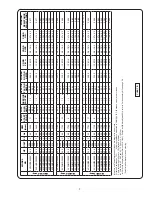
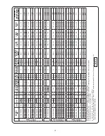
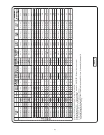
Page 6: ...62 20 0 208 3 60 3450 G 75 8 1 2 87 0 348 0 138319 2 4 18 4 1 47 03 0 077 4XSHVA25092 25 0 208 3 60 3450 G 90 0 1 2 106 0 386 0 138319 2 4 18 4 1 47 03 0 077 230 80 0 94 0 4XSHVA30092 30 0 208 3 60 3450 E 106 0 1 2 128 2 386 0 138319 2 4 18 4 1 47 03 0 077 230 94 0 109 0 4XSHVA40032 40 0 230 3 60 3450 H 116 2 1 2 135 1 658 0 138319 2 4 18 4 1 47 03 047 4XSHVA40042 40 0 460 3 60 3450 H 58 1 1 2 67 ...

Page 7: ... 1 2 126 4 486 0 138319 2 4 18 4 1 47 03 063 4XSHMD40044 40 0 460 3 60 1750 E 53 0 1 2 63 2 243 0 138318 6 4 18 4 1 14 03 248 4XSHMD40054 40 0 575 3 60 1750 E 42 4 1 2 50 6 194 4 138317 8 4 18 4 1 12 02 382 XSHMB Pump 4XSHMB20064 20 0 208 3 60 1750 G 63 0 1 2 74 6 323 0 138318 6 4 18 4 1 14 03 0 88 2 14 4XSHMB25094 25 0 208 3 60 1750 G 77 8 1 2 93 4 359 0 138319 2 4 18 4 1 47 03 0 098 230 71 4 1 2...

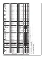
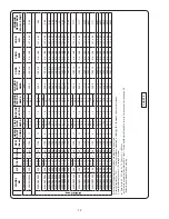
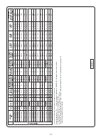
Page 8: ...0 70 8 82 6 4XSHME25046 25 0 460 3 60 1150 G 35 4 1 2 41 3 177 0 138317 8 4 18 4 1 12 02 4397 4XSHME25056 25 0 575 3 60 1150 G 28 3 1 2 33 0 141 6 138317 8 4 18 4 1 12 02 6857 4XSHME30096 30 0 208 3 60 1150 E 90 8 1 2 114 9 354 0 138319 2 4 18 4 1 47 03 1117 230 82 6 99 7 4XSHME30046 30 0 460 3 60 1150 E 41 3 1 2 49 9 177 0 138317 8 4 18 4 1 12 02 4397 4XSHME30056 30 0 575 3 60 1150 E 33 0 1 2 39 ...

Page 9: ...1150 H 60 3 1 2 71 5 354 0 138318 6 4 18 4 1 14 03 1117 230 57 2 69 8 4XSHDI25096 25 0 208 3 60 1150 G 75 2 1 2 90 8 354 0 138319 2 4 18 4 1 47 03 1117 230 70 8 82 6 4XSHDI25046 25 0 460 3 60 1150 G 35 4 1 2 41 3 177 0 138317 8 4 18 4 1 12 02 4397 4XSHDI25056 25 0 575 3 60 1150 G 28 3 1 2 33 0 141 6 138317 8 4 18 4 1 12 02 6857 4XSHDI30096 30 0 208 3 60 1150 E 90 8 1 2 114 9 354 0 138319 2 4 18 4 ...

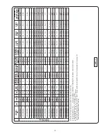
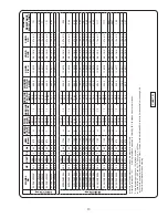
Page 10: ... 208 3 60 1150 H 60 3 1 2 71 5 354 0 138318 6 4 18 4 1 14 03 1117 230 57 2 69 8 6XSHVL25096 25 0 208 3 60 1150 G 75 2 1 2 90 8 354 0 138319 2 4 18 4 1 47 03 1117 230 70 8 82 6 6XSHVL25046 25 0 460 3 60 1150 G 35 4 1 2 41 3 177 0 138317 8 4 18 4 1 12 02 4397 6XSHVL25056 25 0 575 3 60 1150 G 28 3 1 2 33 0 141 6 138317 8 4 18 4 1 12 02 6857 6XSHVL30096 30 0 208 3 60 1150 E 90 8 1 2 114 9 354 0 138319...

Page 11: ...0 E 106 0 1 2 126 4 486 0 138319 2 4 18 4 1 47 03 063 6XSHMH40044 40 0 460 3 60 1750 E 53 0 1 2 63 2 243 0 138318 6 4 18 4 1 14 03 248 6XSHMH40054 40 0 575 3 60 1750 E 42 4 50 6 194 4 138317 8 4 18 4 1 12 02 382 6XSHMH50044 50 0 460 3 60 1750 F 67 1 1 2 79 0 339 0 138318 6 4 18 4 1 14 03 15 6XSHMH50054 50 0 575 3 60 1750 F 53 7 1 2 63 2 271 2 138318 6 4 18 4 1 14 03 245 XSHMJ Pump 6XSHMJ50044 50 0...

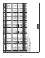
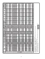
Page 12: ... 4 18 4 1 14 03 245 6XSHDK20096 20 0 208 3 60 1150 H 60 3 1 2 71 5 354 0 138318 6 4 18 4 1 14 03 1117 230 57 2 69 8 6XSHDK25096 25 0 208 3 60 1150 G 75 2 1 2 90 8 354 0 138319 2 4 18 4 1 47 03 1117 230 70 8 82 6 6XSHDK25046 25 0 460 3 60 1150 G 35 4 1 2 41 3 177 0 138317 8 4 18 4 1 12 02 4397 6XSHDK25056 25 0 575 3 60 1150 G 28 3 1 2 33 0 141 6 138317 8 4 18 4 1 12 02 6857 6XSHDK30096 30 0 208 3 6...

Page 13: ...XSHDU50044 50 0 460 3 60 1750 F 67 1 1 2 79 0 339 0 138318 6 4 18 4 1 14 03 15 8XSHDU50054 50 0 575 3 60 1750 F 53 7 1 2 63 2 271 2 138318 6 4 18 4 1 14 03 245 8XSHDU60044 60 0 460 3 60 1750 E 79 0 1 2 95 5 339 0 138319 2 4 18 4 1 47 03 15 8XSHDU60054 60 0 575 3 60 1750 E 63 2 1 2 76 4 271 2 138318 6 4 18 4 1 14 03 245 8XSHDU20096 20 0 208 3 60 1150 H 60 3 1 2 71 5 354 0 138318 6 4 18 4 1 14 03 11...

Page 14: ...058 10 0 575 3 60 870 L 15 4 1 2 16 9 92 0 138317 8 4 18 4 1 12 03 1 27 8XSHTM15098 15 0 208 3 60 870 G 50 4 1 2 59 0 230 0 138317 8 4 18 4 1 12 02 199 230 48 4 55 6 8XSHTM15048 15 0 460 3 60 870 G 24 2 1 2 27 8 115 0 138317 8 4 18 4 1 12 03 795 8XSHTM15058 15 0 575 3 60 870 G 19 4 1 2 22 2 92 0 138317 8 4 18 4 1 12 03 1 27 8XSHTM20098 20 0 208 3 60 870 J 69 0 1 2 76 0 400 0 138318 6 4 18 4 1 14 0...

Page 15: ... 21 1 115 0 138317 8 4 18 4 1 12 02 795 10XSHDW10058 10 0 575 3 60 870 L 15 4 1 2 16 9 92 0 138317 8 4 18 4 1 12 02 1 27 10XSHDW15098 15 0 208 3 60 870 G 50 4 1 2 59 0 230 0 138317 8 4 18 4 1 12 02 199 230 48 4 55 6 10XSHDW15048 15 0 460 3 60 870 G 24 2 1 2 27 8 115 0 138317 8 4 18 4 1 12 02 795 10XSHDW15058 15 0 575 3 60 870 G 19 4 1 2 22 2 92 0 138317 8 4 18 4 1 12 02 1 27 10XSHDW20098 20 0 208 ...

Page 16: ...0 0 138317 8 4 18 4 1 12 02 483 10XSHDX20058 20 0 575 3 60 870 J 30 1 1 2 32 9 160 0 138317 8 4 18 4 1 12 02 77 10XSHDX25098 25 0 208 3 60 870 H 82 3 1 2 98 8 400 0 138319 2 4 18 4 1 47 03 121 230 84 0 94 5 10XSHDX25048 25 0 460 3 60 870 H 42 0 1 2 47 2 200 0 138317 8 4 18 4 1 12 02 483 10XSHDX25058 25 0 575 3 60 870 H 33 6 1 2 37 8 160 0 138317 8 4 18 4 1 12 02 77 10XSHDX30098 30 0 208 3 60 870 F...

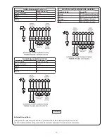
Page 17: ...n Ground Green Black 1 Red 2 White 3 MOISTURE AND TEMPERATURE SENSORS MOISTURE AND TEMPERATURE SENSORS Control Cable Control Cable Lead ID Lead ID Brown P1 Temperature Sensor Yellow P2 Temperature Sensor Orange W1 Moisture Sensor Blue W2 Moisture Sensor FIGURE 3 External Ground Note Grd symbol An external ground screw is provided on the side of the motor cap which can be used for supplemental bond...

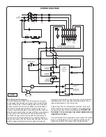
Page 18: ...button of the pilot circuit of the magnetic motor controller located in the control panel so that the thermostat will open the circuit before dangerous temperatures are reached A manual momentary start switch is required to prevent the automatic restarting of the motor when the thermostat resets For a typical wiring diagram refer to Figure 4 In the event of an over temperature condition the source...

Page 19: ...ase or panel mounted and is resistant to noise issues found with some VFD s Indicator lights on the front display notify the operator in the event of a fault condition for either temperature moisture or both Normally open and normally closed contacts are flexible to accommodate nearly any wiring scenario and the moisture sensor sensitivity can be adjusted to prevent nuisance alarms SECTION C START...

Page 20: ...l tester with a range to 30 Kilovolts breakdown 3 If oil is found to be clean and uncontaminated measure above 15 KV breakdown refill the seal chamber as per section E 1 2 4 If oil is found to be dirty or contaminated or measures below 15 KV breakdown the pump must be carefully inspected for leaks at the shaft seal 4 before refilling with oil To locate the leak perform a pressure test as per secti...

Page 21: ...acing seal remove stationary 4A from mounting plate by prying out with flat screw driver E 3 2 Reassembly Lightly oil DO NOT use grease outer surface of stationary member 4A Press stationary member 4A firmly into mounting plate using a seal pusher aligning seal with pin nothing but the seal pusher is to come in contact with seal face See Fig 7 Make sure the stationary member is in straight and tha...

Page 22: ... 3 MODEL NUMBER This designation consists of numbers and letters which rep resent the discharge size series horsepower motor phase and voltage speed and pump design This number is used for ordering and obtaining information F 4 SERIAL NUMBER The serial number block will consist of a six digit number which is specific to each pump and may be preceded by an alpha character which indicates the plant ...

Page 23: ...eller for freedom of operation security and condition Clean impeller and inlet of any obstruction 9 Loosen union slightly to allow trapped air to escape Verify that turn off level of switch is set so that the suction is always flooded Clean vent hole 10 Check rotation If power supply is three phase reverse any two of three power supply leads to ensure proper impeller rotation 11 Repair fixtures as...

Page 24: ...VC 3 00 76 2 3SHVR 3XSHVR 3SHVRA 3XSHVRA 3 50 88 9 3SHMP 3XSHMP 3SHMPA 3XSHMPA 4SHMS 4XSHMS 3 75 95 3 4SHDF 4XSHDF 4SHVA 4XSHVA 4 00 101 6 4SHVB 4XSHVB 4SHVBA 4XSHVBA 4 25 108 4SHMC 4XSHMC 4SHDG 4XSHDG 4SHMD 4XSHMD 4 75 120 7 6SHVL 6XSHVL 5 25 133 4 6SHDO 6XSHDO 5 50 139 7 4SHMB 4XSHMB 6 00 152 4 4SHME 4XSHME 4SHMEA 4XSHMEA 4SHDI 4XSHDI 6SHMN 6XSHMN 6 50 165 1 6SHMH 6XSHMH 6SHMJ 6XSHMJ 6SHDK 6XSHD...

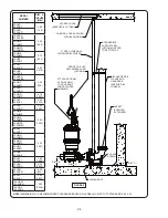
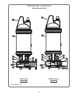
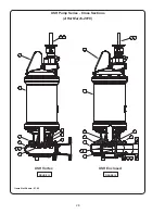
Page 25: ...25 FIGURE 9 XSH Pump Series Cross Sections Before March 2016 FIGURE 10 XSH Vortex XSH Enclosed Items Not Shown 41 42 ...

Page 26: ... RC 603 TORQUE TO 45 1 4 FT LBS CORD ENTRY BOLTS TORQUE TO 35 FT LBS MUST BE METAL TO METAL 23 1 2 7 6 9 8 8A 10 11 APPLY GREEN LOCTITE RC 603 TORQUE TO 45 1 4 FT LBS APPLY GREEN LOCTITE TO O D OF WEAR RING CORD ENTRY BOLTS TORQUE TO 35 FT LBS MUST BE METAL TO METAL FIGURE 11 FIGURE 12 XSH Vortex XSH Enclosed Items Not Shown 41 42 ...

Page 27: ... 1 130063 Ring Retaining EXT 5100 187 H 23 1 125458 Handle Lifting SS 304 SS 41 5oz 125502 Paint Epoxy Part A Epoxy 42 5oz 125503 Paint Epoxy Part B Epoxy SH Pump Fixed Cord Assemblies Before March 2016 Part No Length feet Cord Size Cord O D 130906XF 50 8 4 18 4 1 12in 02in 28 4mm 5mm 130906XJ 75 8 4 18 4 1 12in 02in 28 4mm 5mm 130906XL 100 8 4 18 4 1 12in 02in 28 4mm 5mm 130907XF 50 6 4 18 4 1 14...

Page 28: ...28 FIGURE 13 XSH Pump Series Cross Sections After March 2016 FIGURE 14 XSH Vortex XSH Enclosed Items Not Shown 61 62 ...

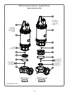
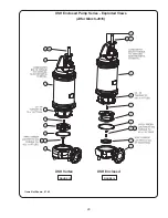
Page 29: ...29 XSH Enclosed Pump Series Exploded Views After March 2016 FIGURE 15 FIGURE 16 XSH Vortex XSH Enclosed Items Not Shown 61 62 ...

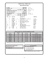
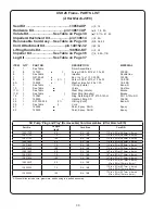
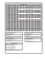
Page 30: ...ar Ring Impeller Bronze 19 1 130063 Ring Retaining EXT 5100 187 H PH 15 7 Mo SS 23 1 138550 Handle Lifting SS 304 SS 56 1 2 31003 248 β π O Ring Cord Buna N 59 1 See Table β Cord 61 125502 Paint Epoxy Part A Epoxy 62 125503 Paint Epoxy Part B Epoxy SH Pump Plug and Play Removeable Cord Assemblies After March 2016 Part No Length feet Cord Size Cord O D 138317XF 50 8 4 18 4 1 12in 02in 28 4mm 5mm 13...

Page 31: ...SHMN 370mm 130830 138603 130833 125857 360 6XSHMH 370mm 130830 138603 130833 125857 360 6XSHMJ 370mm 130830 138603 130833 125857 360 6XSHDO 305mm 138110 140146 130834 125857 295 6XSHDK 370mm 130830 138604 130834 125857 360 8XSHVV 465mm 138107 140147 N A M 6614 8XSHDU 305mm 138108 140148 138999 125857 295 8XSHTM 370mm 130832 138607 130836 125857 360 10XSHDW 370mm 138106 140149 139001 125857 360 10X...

Page 32: ...3272TN 135mm 5 31in 125454TP 143272TP 130mm 5 12in 125454TR 143272TR 125mm 4 92in 125454TS 143272TS B Impeller Trim Dia mm in Ductile Iron Part No Nihard Part No 185mm 7 28in 125456 143273 180mm 7 09in 125456TA 143273TA 175mm 6 89in 125456TB 143273TB 170mm 6 69in 125456TC 143273TC 165mm 6 50in 125456TD 143273TD 160mm 6 30in 125456TE 143273TE 155mm 6 10in 125456TF 143273TF 150mm 5 91in 125456TG 143...

Page 33: ...60in 129993TK 143278TK 315mm 12 40in 129993TL 143278TL 310mm 12 20in 129993TM 143278TM 305mm 12 01in 129993TN 143278TN 300mm 11 81in 129993TP 143278TP 295mm 11 61in 129993TR 143278TR 290mm 11 42in 129993TS 143278TS 285mm 11 22in 129993TT 143278TT 280mm 11 02in 129993TU 143278TU 275mm 10 83in 129993TV 143278TV 270mm 10 63in 129993TW 143278TW 265mm 10 43in 129993TX 143278TX 260mm 10 24in 129993TY 14...

Page 34: ...n 130828TK 143283TK 275mm 10 83in 130828TL 143283TL 270mm 10 63in 130828TM 143283TM 265mm 10 43in 130828TN 143283TN 260mm 10 24in 130828TP 143283TP 255mm 10 04in 130828TQ 143283TQ 250mm 9 84in 130828TR 143283TR 245mm 9 65in 130828TS 143283TS 240mm 9 45in 130828TT 143283TT 235mm 9 25in 130828TU 143283TU 230mm 9 06in 130828TV 143283TV 225mm 8 86in 130828TW 143283TW 220mm 8 66in 130828TX 143283TX 215...

Page 35: ...3294UB 320mm 12 60in 138101UC 143294UC 315mm 12 40in 138101UD 143294UD 310mm 12 20in 138101UE 143294UE V Impeller Trim Dia mm in Ductile Iron Part No Nihard Part No 455mm 17 91in 138101 143294 450mm 17 72in 138101TA 143294TA 445mm 17 52in 138101TB 143294TB 440mm 17 32in 138101TC 143294TC 435mm 17 13in 138101TD 143294TD 430mm 16 93in 138101TE 143294TE 425mm 16 73in 138101TF 143294TF 420mm 16 54in 1...

Page 36: ...TD 345 13 58in 137225TE 143289TE 340 13 39in 137225TF 143289TF 335 13 19in 137225TG 143289TG 330 13 00in 137225TH 143289TH 325 12 80in 137225TJ 143289TJ 320 12 60in 137225TK 143289TK 315 12 40in 137225TL 143289TL 310 12 20in 137225TM 143289TM 305 12 01in 137225TN 143289TN 300 11 81in 137225TP 143289TP 295 11 61in 137225TR 143289TR MB Impeller Trim Dia mm in Ductile Iron Part No Nihard Part No 320m...

Page 37: ...n 138099TY KIT 143296TY U Impeller Trim Dia mm in Ductile Iron Part No Nihard Part No 305mm 12 00in 138102S KIT 143293S 300mm 11 81in 138102STA KIT 143293STA 295mm 11 61in 138102STB KIT 143293STB 290mm 11 42in 138102STC KIT 143293STC 285mm 11 22in 138102STD KIT 143293STD 280mm 11 02in 138102STE KIT 143293STE 275mm 10 82in 138102STF KIT 143293STF 270mm 10 63in 138102STG KIT 143293STG 265mm 10 43in ...

Page 38: ...DI 125506B 6 50 165 6XSHMN 125506B 6 50 165 6XSHMH 125506B 6 50 165 6XSHMJ 125506B 6 50 165 6XSHDK 125506B 6 50 165 6XSHVT 125506B 6 50 165 8XSHDU 125506B 6 50 165 8XSHTM 125506C 10 75 273 8XSHVV 125506C 10 75 273 10XSHDW 125506C 10 75 273 10XSHDX 125506C 10 75 273 Leg Kit includes 3 Legs painted attachement hardware Additional Components Component Part No Single Sale Kit Impeller See Table Yes N ...

Page 39: ...N A 140152 28 138550 KIT 3XSHVRA50042 138582 XP 138617 XP 139231 138614 125506 N A N A 140152 28 138550 KIT 3XSHVRA50052 138582 XP 138617 XP 139231 138614 125506 N A N A 140152 28 138550 KIT 4XSHVA20062 138582 XP 138617 XP 138597 138614 N A 125506 140152 28 125458 KIT 140152 32 138550 KIT 4XSHVA25092 138582 XP 138617 XP 138597 138614 N A 125506 140152 28 125458 KIT 140152 32 138550 KIT 4XSHVA30092...

Page 40: ...52 32 138550 KIT 4XSHMB40034 138582 XP 138617 XP 138600 138614 N A 125506B NA N A 140152 32 138550 KIT 4XSHMB40044 138582 XP 138617 XP 138600 138614 N A 125506B NA N A 140152 32 138550 KIT 4XSHMB40054 138582 XP 138617 XP 138600 138614 N A 125506B NA N A 140152 32 138550 KIT 4XSHMB50044 138582 XP 138617 XP 138600 138614 N A 125506B NA N A 140152 32 138550 KIT 4XSHMB50054 138582 XP 138617 XP 138600 ...

Page 41: ... 4XSHDI50044 138582 XP 138617 XP 138600 138614 N A 125506B 140152 28 125458 KIT 140152 32 138550 KIT 4XSHDI50054 138582 XP 138617 XP 138600 138614 N A 125506B 140152 28 125458 KIT 140152 32 138550 KIT 4XSHDI60044 138582 XP 138617 XP 138600 138614 N A 125506B 140152 28 125458 KIT 140152 32 138550 KIT 4XSHDI60054 138582 XP 138617 XP 138600 138614 N A 125506B 140152 28 125458 KIT 140152 32 138550 KIT...

Page 42: ...506 140152 28 125458 KIT 140152 32 138550 KIT 6XSHVL25056 138582 XP 138617 XP 138606 138614 N A 125506 140152 28 125458 KIT 140152 32 138550 KIT 6XSHVL30096 138582 XP 138617 XP 138606 138614 N A 125506 140152 28 125458 KIT 140152 32 138550 KIT 6XSHVL30046 138582 XP 138617 XP 138606 138614 N A 125506 140152 28 125458 KIT 140152 32 138550 KIT 6XSHVL30056 138582 XP 138617 XP 138606 138614 N A 125506 ...

Page 43: ...XSHMH50044 138582 XP 138617 XP 138603 138614 N A 125506B 140152 28 125458 KIT 140152 32 138550 KIT 6XSHMH50054 138582 XP 138617 XP 138603 138614 N A 125506B 140152 28 125458 KIT 140152 32 138550 KIT 6XSHMJ50044 138582 XP 138617 XP 138603 138614 N A 125506B 140152 28 125458 KIT 140152 32 138550 KIT 6XSHMJ50054 138582 XP 138617 XP 138603 138614 N A 125506B 140152 28 125458 KIT 140152 32 138550 KIT 6...

Page 44: ...25506B 140152 28 125458 KIT 140152 32 138550 KIT 6XSHDK60044 138582 XP 138617 XP 138604 138614 N A 125506B 140152 28 125458 KIT 140152 32 138550 KIT 6XSHDK60054 138582 XP 138617 XP 138604 138614 N A 125506B 140152 28 125458 KIT 140152 32 138550 KIT 6XSHDK20096 138582 XP 138617 XP 138604 138614 N A 125506B 140152 28 125458 KIT 140152 32 138550 KIT 6XSHDK25096 138582 XP 138617 XP 138604 138614 N A 1...

Page 45: ...58 KIT 140152 32 138550 KIT 8XSHDU40044 138582 XP 138617 XP 140148 138614 125506B 140152 28 125458 KIT 140152 32 138550 KIT 8XSHDU40054 138582 XP 138617 XP 140148 138614 125506B 140152 28 125458 KIT 140152 32 138550 KIT 8XSHDU50044 138582 XP 138617 XP 140148 138614 125506B 140152 28 125458 KIT 140152 32 138550 KIT 8XSHDU50054 138582 XP 138617 XP 140148 138614 125506B 140152 28 125458 KIT 140152 32...

Page 46: ...XSHTM10098 138582 XP 138617 XP 138607 138614 N A 125506C 140152 28 125458 KIT 140152 32 138550 KIT 8XSHTM10048 138582 XP 138617 XP 138607 138614 N A 125506C 140152 28 125458 KIT 140152 32 138550 KIT 8XSHTM10058 138582 XP 138617 XP 138607 138614 N A 125506C 140152 28 125458 KIT 140152 32 138550 KIT 8XSHTM15098 138582 XP 138617 XP 138607 138614 N A 125506C 140152 28 125458 KIT 140152 32 138550 KIT 8...

Page 47: ... KIT 10XSHDW20048 138582 XP 138617 XP 140149 138614 125506C 140152 28 125458 KIT 140152 32 138550 KIT 10XSHDW20058 138582 XP 138617 XP 140149 138614 125506C 140152 28 125458 KIT 140152 32 138550 KIT 10XSHDW25098 138582 XP 138617 XP 140149 138614 125506C 140152 28 125458 KIT 140152 32 138550 KIT 10XSHDW25048 138582 XP 138617 XP 140149 138614 125506C 140152 28 125458 KIT 140152 32 138550 KIT 10XSHDW...

Page 48: ...Notes ...
Page 49: ...A RETURNED GOODS AUTHORIZATION CONTACT YOUR LOCAL CRANE PUMPS SYSTEMS INC DISTRIBUTOR Products Returned Must Be Cleaned Sanitized Or Decontaminated As Necessary Prior To Shipment To Insure That Employees Will Not Be Exposed To Health Hazards In Handling Said Material All Applicable Laws And Regulations Shall Apply IMPORTANT WARRANTY REGISTRATION Your product is covered by the enclosed Warranty If ...

Reviews: