background image

10

Position unit upright, using blocks to avoid resting unit on 
shaft. Unscrew cord hex bolts (6) and remove compression 
fl ange (10a) and power cord (10). Remove snap ring (8) with 
a fl at head screwdriver. Pull the terminal block (27) out of the 
motor housing (2) using a T-bolt or pair of pliers and a .25-20 
screw in the threads of the terminal block (27). Be sure to 
leave slack on the motor leads connected underneath. Use 
needle nose pliers to pull each female connector off of the 
pins on the underside of the terminal block (27) (see Figure 
6). The unit voltage should be noted. Remove socket head 
cap screws (39). Vertically lift upper pump assembly from 
seal plate (25) by lifting handle (7). Inspect square rings (42) 
for damage or cuts. 

Motor - 

Remove the motor bolts and lift motor stator from 

motor rotor and seal plate (25). Unscrew conduit bushing (14) 
from seal plate (25) and lift motor rotor, shaft, bearing (42), 
rotating portion of seal (46), washer (9) and conduit bushing 
(14) from seal plate (25).

Inspect windings for shorts and check resistance values. 
Check rotor for wear, if rotor or the stator windings are 
defective, the complete motor must be replaced. To test 
the temperature sensor (if equipped), check the continuity 
between the black and white wires. If found to be defective 
contact a motor service station or CP&S Service Department. 

Check motor capacitor (3, 1 phase units) with an Ohm meter 

by fi rst grounding the capacitor by placing a screwdriver 
across both terminals and then removing screwdriver.  
Connect Ohm meter (set on high scale) to terminals. If needle 
moves to infi

 nity (∞) then drifts back, the capacitor is good. 

If needle does not move or moves to infi nity (∞) and does 
not drift back, replace capacitor (3). To test the temperature 
sensor (P1/P2), check for continuity between the wire leads 
(see Figure 10). If found to be defective, contact a motor 
service station or CP&S Pumps Service department. Inspect 
motor winding for shorts and check resistance values. Check 
rotor for wear. If rotor or the stator windings are defective, the 
complete motor must be replaced.

Important! - Handle seal parts with extreme care. 
Do Not scratch or mar lapped surfaces.

Seal - 

Remove rotating member (46a), spring (46c) and 

retaining ring (46d) from shaft. (see Figure 3). Examine all 
seal parts and especially contact faces. Inspect seal for signs 
of wear such as uneven wear pattern on stationary members, 
chips and scratches on either seal face. 

DO NOT

 interchange 

seal components, replace the entire shaft seal (46). If 
replacing seal, remove stationary (46a) from seal plate (25) 
by prying out with fl at screwdriver.

Bearing - 

Examine bearing (47) and replace if required. If 

replacement is required, remove bearing (47) from motor 
shaft using a wheel puller. Washer (9), retaining ring (30) and 
conduit bushing (14) can now be removed from motor shaft.

Important ! - All parts must be clean before 
reassembly.

F-3.2) Reassembly:
Bearing -

 When replacing bearing, be careful not to damage 

the rotor or shaft threads. Clean the shaft thoroughly. Slide 
conduit bushing (14) and washer (9) over motor shaft. Insert 
retaining ring (30) into groove on shaft. Apply adhesive 
compound to the shaft and press bearing (47) on the motor 
shaft, position squarely onto shaft applying force to the inner 
race of the bearing only, until bearing seats against retaining 
ring (30).

Seal -

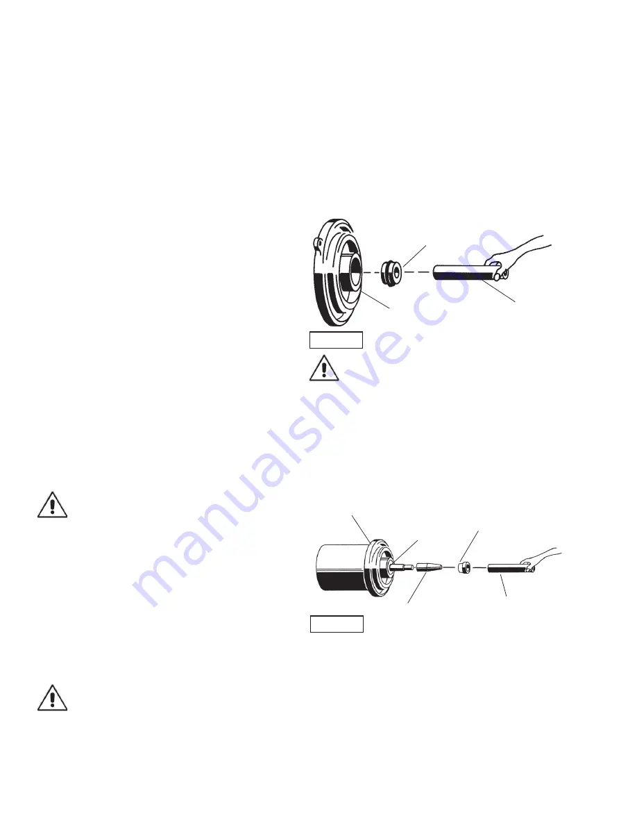
 Clean and oil seal cavity in seal plate (25). Press 

stationary member (46a) fi rmly into seal plate (25), using a 
seal pusher, nothing but the seal pusher is to come in contact 
with seal face (See Figure 6). Make sure the stationary 
member is in straight.

Important! - DO NOT hammer on the seal pusher 

it will damage the seal face.

Slide retaining ring (46d) over shaft and let rest on bearing 
(47). Place spring (46c) over shaft and let rest on retaining 
ring (46d). Lightly oil (DO NOT use grease) shaft, bullet and 
inner surface of bellows on rotating member (46b) (See 
Figure 7), with lapped surface of rotating member (46b) 
facing outward, slide over bullet and onto shaft using seal 
pusher, making sure spring (46c) is seated in retaining ring 
(46d) and spring (46c) is lined up on rotating member (46b) 
and not cocked or resting on bellows tail.

Motor - 

Slide motor rotor with conduit bushing (14), washer 

(9), bearing (47) and seal parts (46b, c, d) into seal plate (25) 
until bearing (47) seats in seal plate (25). Center washer (9) 
on bearing (47) and tighten conduit bushing (14) on seal plate 
(25). Lower motor stator over rotor until seated in seal plate 
(25), while aligning holes for motor bolts. Insert motor bolts 
and torque to 22 inch pounds. If pump is a single phase unit 
place bracket (15) on one of the motor bolts positioned so 
capacitor will lay on opposite side of the cord entry bosses 
of the motor housing (2). Insert capacitor (3) in bracket (15), 
attach motor leads with terminals to capacitor.

FIGURE 6

Stationary Member (46A) 
Polished Face Out

Seal Plate (25)

Seal Pusher

Rotating Member (46D)

Bullet

Motor & Seal Plate

Seal Pusher

Stationary

FIGURE 7

Summary of Contents for Barnes 3SE3024L

Page 1: ...ovement program product changes may occur As such Crane Pumps Systems reserves the right to change product without prior written notification 420 Third Street 83 West Drive Brampton Piqua Ohio 45356 Ontario Canada L6T 2J6 Phone 937 778 8947 Phone 905 457 6223 Fax 937 773 7157 Fax 905 457 2650 www cranepumps com Form No 133410 Rev C Series 3SE L 3HP 3450RPM 60Hz Series 3SE L 3HP 1750RPM 60Hz Single...

Page 2: ...ST 3SE L 3450RPM 16 17 CROSS SECTION 3SE L 1750RPM Fig 11 18 EXPLODED VIEW 3SE L 1750RPM Fig 12 19 PARTS LIST 3SE L 1750RPM 20 21 WARRANTY 22 WARRANTY REGISTRATION 23 RETURNED GOODS POLICY 23 SPECIAL TOOLS AND EQUIPMENT INSULATION TESTER MEGGER DIELECTRIC TESTER SEAL TOOL KIT see parts list PRESSURE GAUGE KIT see parts list Other brand and product names are trademarks or registered trademarks of t...

Page 3: ...OT insert fingers in pump with power connected Always wear eye protection when working on pumps Make sure lifting handles are securely fastened each time before lifting DO NOT operate pump without safety devices in place Always replace safety devices that have been removed during service or repair Secure the pump in its operating position so it can not tip over fall or slide DO NOT exceed manufact...

Page 4: ...orque Curve Oil Filled Squirrel Cage Induction Insulation Class B THREE PHASE 200 230 460 60Hz is Tri voltage motor 575V Requires overload protection to be included in control panel OPTIONAL EQUIPMENT Seal Material Impeller Trims Additional Cord SECTION A PUMP SPECIFICATIONS 3450RPM 21 78 553 6 34 161 3 00 N P T DISCHARGE 2 13 54 11 05 281 3 29 84 14 68 373 7 32 186 inches mm IMPORTANT 1 PUMP MAY ...

Page 5: ... PLATE Cast Iron ASTM Class 30 IMPELLER Design 2 Vane Semi open with Pump out vanes on Back side Dynamically balanced ISO G6 3 Material Cast Iron Class 30 SHAFT 416 Stainless Steel SQUARE RINGS Buna N HARDWARE 300 Series Stainless Steel PAINT Air dry enamel top coat SEAL Design Single Mechanical in oil filled reservoir Material Rotating Faces Carbon Stationary Faces Ceramic Elastomer Buna N Hardwa...

Page 6: ... basin shall be vented in accordance with local plumbing codes This pump is designed to pump sewage effluent or other nonexplosive or noncorrosive wastewater and shall NOT be installed in locations classified as Class I Division 1 hazardous in accordance with the National Electrical Code NEC ANSI NFPA 70 or The Canadian Electrical Code Never install the pump in a trench ditch or hole with a dirt b...

Page 7: ...es Inrush Amperes 220 240 1 50 15 0 440 480 0 75 7 5 575 600 0 60 6 0 C 4 4 Wire Size Consult a qualified electrician for proper wire size if additional power cable length is required See table for electrical information SECTION D START UP OPERATION D 1 Check Voltage and Phase Before operating pump compare the voltage and phase information stamped on the pump identification plate to the available ...

Page 8: ...15 KV breakdown the the pump must be carefully inspected for leaks at the shaft seal 46 cord assemblies 10 and 11 if used square ring 42 and pipe plugs 5 before refilling with oil To locate the leak perform a pressure test as per section F 1 4 After leak is repaired refill with new oil as per section F 1 3 F 1 3 Replacing Oil Motor Housing Set unit upright and refill with new cooling oil as per Ta...

Page 9: ...Figure 9 and 10 F 2 2 Reassembly To install impeller 28 apply a thin film of oil to motor shaft and slide impeller straight onto shaft keeping keyways lined up Drive key 33 into keyway Locate washer 35 apply thread locking compound to shaft threads thread hex nut 34 to shaft and torque to 40 ft lbs Rotate impeller to check for binding Position square ring 42 on volute flange and position impeller ...

Page 10: ...stationary members chips and scratches on either seal face DO NOT interchange seal components replace the entire shaft seal 46 If replacing seal remove stationary 46a from seal plate 25 by prying out with flat screwdriver Bearing Examine bearing 47 and replace if required If replacement is required remove bearing 47 from motor shaft using a wheel puller Washer 9 retaining ring 30 and conduit bushin...

Page 11: ...in paragraph F 1 4 Make wire connections as outlined in paragraph F 3 3 Insert female end of cord plug into housing bore aligning timing mark with hole in terminal block 27 see Figure 5 Compress cord plug with compression flange 10a by tightening cap screws 24 into the motor housing 2 Torque to 132 in lbs SECTION G REPLACEMENT PARTS G 1 ORDERING REPLACEMENT PARTS When ordering replacement parts AL...

Page 12: ...12 FIGURE 10 ...

Page 13: ...rity and condition Clean impeller and inlet of any obstruction 9 Loosen union slightly to allow trapped air to escape Verify that turn off level of switch is set so that the suction is always flooded Clean vent hole 10 Check rotation If power supply is three phase reverse any two of three power supply leads to ensure proper impeller rotation 11 Repair fixtures as required to eliminate leakage 12 C...

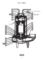
Page 14: ...14 FIGURE 11 3SE L 3450RPM ...

Page 15: ...15 26 24 43 42 34 35 44 28 39 49 16 17 46 25 42 47 33 9 14 30 1 29 21 18 23 22 19 20 2 5 45 7 4 6 43 12 48 27 8 10 4 6 43 11 FIGURE 12 3SE L 3450RPM ...

Page 16: ...or Housing 14 1 053749 Conduit Bushing 16 1 062641 Pull Washer 17 1 061829 Exclusion Seal Buna N 18 1 016660 Self Tap Screw 19 4 20 14 1 3 8 Lock washer SS 20 4 15 23 1 3 8 16 Hex Nut SS 21 1 105111B Ground Wire 12AWG x 8 00 LG 230V 3 Phase 1 105111 Ground Wire 14AWG x 8 00 LG 460 575V 3 Phase 22 1 625 02117 Fiberglass Sleeve 460 575V 3 Phase 2 625 02117 Fiberglass Sleeve 230V 3 Phase 23 1 105150 ...

Page 17: ...005 use as required 1 026989 Shim 010 use as required 3 028121 Shim 030 use as required TABLE 2 POWER AND SENSOR CORD SETS MODEL NUMBER 30 FT POWER 50 FT POWER 100 FT POWER TERMINAL BLOCK POWER 3SE3032L 109492XC 109492XF 109492XL 103586 3SE3042L 103742XC 103742XF 103742XL 103583 3SE3052L 103742XC 103742XF 103742XL 103583 MODEL NUMBER 30 FT SENSOR 50 FT SENSOR 100 FT SENSOR TERMINAL BLOCK SENSOR 3S...

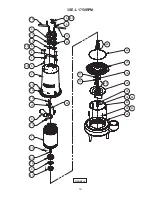
Page 18: ...18 3SE L 1750RPM FIGURE 13 ...

Page 19: ...19 26 46 24 42 34 35 28 49 39 17 16 25 42 47 9 14 30 33 1 3 15 21 18 19 20 2 5 7 4 6 12 27 48 8 10 11 4 6 43 44 22 45 43 43 FIGURE 14 3SE L 1750RPM ...

Page 20: ...0 oz 029034 Oil Motor Housing 14 1 053749 Conduit Bushing 15 1 133495 Bracket Capacitor 16 1 062641 Pull Washer 17 1 061829 Exclusion Seal 18 1 016660 Self Tap Screw 19 4 20 14 1 3 8 Lock washer SS 20 4 15 23 1 3 8 16 Hex Nut SS 21 1 105111A Ground Wire Green 10AWG x 8 00 LG 230V 1 Phase 1 105111B Ground Wire Green 12AWG x 8 00 LG 230V 3 Phase 1 105111 Ground Wire Green 14AWG x 8 00 LG 460 575V 3 ...

Page 21: ...ll Bearing 48 1 See Table 3 Optional Sensor Cord Terminal Block 49 2 026989 Shims 005 use as required 2 028120 Shims 010 use as required TABLE 3 POWER AND SENSOR CORD SETS MODEL NUMBER 30 FT POWER 50 FT POWER 100 FT POWER TERMINAL BLOCK POWER 3SE3024L 103769XC 103769XF 103769XL 103760 3SE3034L 109492XC 109492XF 109492XL 103586 3SE3044L 103742XC 103742XF 103742XL 103583 3SE3054L 103742XC 103742XF 1...

Page 22: ...es between the results of eld testing conducted by or for user and laboratory tests corrected for eld performance the latter shall control RECOMMENDATIONS FOR SPECIAL APPLICATIONS OR THOSE RESULTING FROM SYSTEMS ANALYSES AND EVALUATIONS WE CONDUCT WILL BE BASED ON OUR BEST AVAILABLE EXPERIENCE AND PUBLISHED INDUSTRY INFORMATION SUCH RECOMMENDATIONS DO NOT CONSTITUTE A WARRANTY OF SATISFACTORY PERF...

Page 23: ...ent To Insure That Employees Will Not Be Exposed To Health Hazards In Handling Said Material All Applicable Laws And Regulations Shall Apply IMPORTANT WARRANTY REGISTRATION Your product is covered by the enclosed Warranty To complete the Warranty Registration Form go to http www cranepumps com ProductRegistration If you have a claim under the provision of the warranty contact your local Crane Pump...

Page 24: ...24 Notes ...

Reviews: