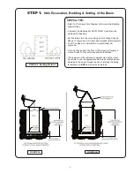
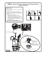
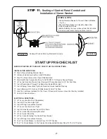
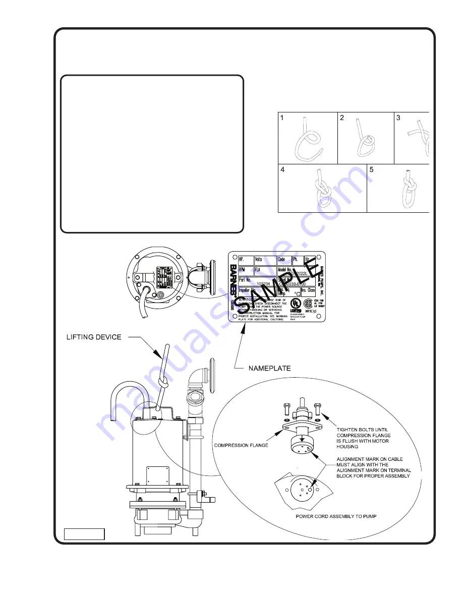
background image

13

STEP 6.

  Remove Parts Box from Basin, Attach Rope to Pumps,

Record Pump Data

STEPS & TIPS:


Remove Parts Box from inside basin. It should contain 

the following items 

• Lifting device, inlet fitting and vent (If required) 

• Remove Connector Protectors From Cord and Pump. 

• Record pump information on user guide for future 

  reference. 

• Attach lifting device to pump.

1. Make a small overhand loop in the rope.

2. Bring the short end through the overhand loop.

3. Place short end behind the fixed part of the rope.

4. Bring end around and back into the loop.

5. Pull on the fixed end of the rope away from the loop

        to tighten the knot. 

• Plug Cord Into Pump As Shown Below.


NEVER LOWER OR RAISE PUMP BY THE CORD!

FIGURE 9

For Illustration Purposes Only.

Summary of Contents for Barnes OGV Series

Page 1: ...Systems reserves the right to change product without prior written notification 420 Third Street 83 West Drive Bramton Piqua Ohio 45356 Ontario Canada L6T 2J6 Phone 937 778 8947 Phone 905 457 6223 Fax 937 773 7157 Fax 905 457 2650 www cranepumps com Form No 109298 Rev H Simplex For Series SGV OGV SGPC Pumps For Easy Identification Pumps used with these basin package will have one cords SUPERSEDED ...

Page 2: ...k outs minimize water consumption at the home s to prevent sewage from backing up into the house Always keep the shut off valve completely open when system is in operation unless advised otherwise by the proper authorities Before removing the pump from the basin be sure to close the shut off valve This prevents backflow from the pressure sewer Keep the control panel locked or confined to prevent u...

Page 3: ...is the Barnes UltraGRIND grinder pump station The basin collects all wastewater from the house The solids in the sewage are then ground to a small size suitable for pumping in the slurry The grinder pump generates sufficient pressure to pump this slurry from your home to the wastewater plant Power Failure Your grinder pump cannot dispose of wastewater or provide an alarm signal without electrical ...

Page 4: ...E STARTING YOUR INSTALLATION SEE TOOL AND MATERIAL LISTS DETERMINE THE BALLAST REQUIREMENTS FOR YOUR PARTICULAR BASIN SIZE SEE CHART 1 USE ONLY THE ELECTRIC CABLE SPECIFIED IN CHART 2 DO NOT USE ANY OTHER CABLE TOOLS REQUIRED LIST NOT INCLUDED 9 16 WRENCH REGULAR SCREWDRIVER HOLESAW FOR INLET SEE CHART ON PAGE 5 WIRE STRIPPERS 10 AWG TO 18AWG PIPE WRENCH CORD OR CORDLESS DRILL CHANNEL LOCKS NEEDLE...

Page 5: ...QUIRED FOR LEVEL CONTROL PUMP SENSOR Standard Floats FloatTREE or UltraSWITCH PUMPS w NO sensor 18 6 IMPORTANT Direct Burial Cable MUST be UL Approved Type TC ROUND Flat type UF cable WILL NO WORK Use of it will VOID WARRANTY Conductor sizes based on maximum 300 Ft length Consult factory for longer lengths CHART 3 INLET SPECIFICATIONS INLET PIPE SIZE HOLE SAW SIZE FLEXIBLE INLET COLOR 1 25 SCH40 3...

Page 6: ...6 Location of Basin And Control Panel FIGURE 1 ...

Page 7: ...ift The Basin On Units With Pre cast Ballast Per Figure 3b Once Set Make Sure The Rim Of The Basin Is Roughly 2 Above Grade To Prevent Ground Water Infiltration If the basin must be removed to adjust hole depth or level be certain to use the appropriate method as outlined above Damage to the basin through the use of improper handling techniques will NOT be warranted by Barnes STEP 1 Hole Excavatio...

Page 8: ...ndant Check Valve Backfill Around The Basin per specifiation ASTM D2321 Backfill Around The Basin To A Level Just Below Where The Inlet Will Enter The Basin All discharge piping and valves should be below local frost depth If burial depth is above frost depth piping should be insulated Before hydrostatic checking of lateral line 150 PSI Max close the shut off valve inside the station This will avo...

Page 9: ...5A STEPS TIPS All penetrations though the basin MUST be sealed watertight Cord grip penetrations MUST be made using a drill and appropriate tap Inlet Not Yet Connected Shown For Reference Only Allow approximately 7 feet of cable inside the basin to allow for wiring and cover removal ...

Page 10: ...CVP Direct Burial Cable to Control Panel STEPS TIPS Check for nicks or damage to wire prior to installation Ensure wire is secure into terminal strip by pulling on wire after installation Place a strip of green electrical tape on the ground wire FIGURE 6 ...

Page 11: ...VH Direct Burial Cable to Control Panel STEPS TIPS Check for nicks or damage to wire prior to installation Ensure wire is secure into terminal strip by pulling on wire after installation Place a strip of green electrical tape on the ground wire FIGURE 7 ...

Page 12: ...ting Level Control Leads Direct Burial Cable to Control Panel STEPS TIPS Check for nicks or damage to wire prior to installation Ensure wire is secure into terminal strip by pulling on wire after installation FIGURE 8 ...

Page 13: ...Record pump information on user guide for future reference Attach lifting device to pump 1 Make a small overhand loop in the rope 2 Bring the short end through the overhand loop 3 Place short end behind the fixed part of the rope 4 Bring end around and back into the loop 5 Pull on the fixed end of the rope away from the loop to tighten the knot Plug Cord Into Pump As Shown Below NEVER LOWER OR RAI...

Page 14: ...nto basin Secure pump cord s and hose assembly so they will not fall into basin and lower into basin Follow all O S H A guidelines Align the lower and upper guide brackets into the rail and lower pump into basin using the lifting device NEVER LOWER OR RAISE PUMP BY THE CORD STEP 7 Sliding Pump Into Basin ...

Page 15: ...rations Shown Inspect Wires for nicks or Defects Before Installing into the Junction Box Lubrication May Be Needed to Help Install Wires Through the Grommets Secure Wire Connections with Appropriate Size Wire Nut Check That Connection is Secure by pulling on Wires After Installed Place a Strip of Green Electrical Tape on The Ground Wire Cable Jacket Should be Slightly Inside of Junction Box ...

Page 16: ... Inspect Wires for nicks or Defects Before Installing into the Junction Box Lubrication May Be Needed to Help Install Wires Through the Grommets Secure Wire Connections with Appropriate Size Wire Nut Check That Connection is Secure by pulling on Wires After Installed Place a Strip of Green Electrical Tape on The Ground Wire Cable Jacket Should be Slightly Inside of Junction Box FIGURE 12 ...

Page 17: ... Shown Inspect Wires for nicks or Defects Before Installing into the Junction Box Lubrication May Be Needed to Help Install Wires Through the Grommets Secure Wire Connections with Appropriate Size Wire Nut Check That Connection is Secure by pulling on Wires After Installed Place a Strip of Green Electrical Tape on The Ground Wire Cable Jacket Should be Slightly Inside of Junction Box FIGURE 13 ...

Page 18: ...wn Inspect Wires for nicks or Defects Before Installing into the Junction Box Lubrication May Be Needed to Help Install Wires Through the Grommets Secure Wire Connections with Appropriate Size Wire Nut Check That Connection is Secure by pulling on Wires After Installed Place a Strip of Green Electrical Tape on The Ground Wire Cable Jacket Should be Slightly Inside of Junction Box FIGURE 14 ...

Page 19: ...s Shown Inspect Wires for nicks or Defects Before Installing into the Junction Box Lubrication May Be Needed to Help Install Wires Through the Grommets Secure Wire Connections with Appropriate Size Wire Nut Check That Connection is Secure by pulling on Wires After Installed Place a Strip of Green Electrical Tape on The Ground Wire Cable Jacket Should be Slightly Inside of Junction Box FIGURE 15 ...

Page 20: ...own Inspect Wires for nicks or Defects Before Installing into the Junction Box Lubrication May Be Needed to Help Install Wires Through the Grommets Secure Wire Connections with Appropriate Size Wire Nut Check That Connection is Secure by pulling on Wires After Installed Place a Strip of Green Electrical Tape on The Ground Wire Cable Jacket Should be Slightly Inside of Junction Box FIGURE 16 ...

Page 21: ...ng this part of the installation Check for nicks or defects in cable and wires A GFI type breaker should NOT be used A separate ground and neutral are required for proper operation Pull on wire once connected to ensure they are secure STEP 9 Power To Control Panel FIGURE 17 ...

Page 22: ...Per Foot Drop If required only use 45 elbows Proper Backfill Per ASTM D2321 Should Be Done To Prevent Damage From Excessive Settling As Outlined for Bedding Backfill Material Should Be Free Of Large Rocks Ice And Trash Slope Finish Grade Away From Basin FIGURE 19 FIGURE 18 FIGURE 20 See CHART 3 on page 5 for inlet hole saw size Shaded Area is Suitable Inlet Zone ...

Page 23: ...And Have A 1 8 Per Foot Drop Are All Penetrations Through The Basin Wall Sealed Water tight Are All Piping Connections Tight And Required Valves Installed Properly Has A Minimum Of 32 Inches Of Water Been Put Into The Tank Has The Vent Been Installed On The Cover If Required Polycover Have Vent Factory Installed Varify All Valves Are Open ELECTRICAL QUESTIONS Is The Junction Box Dry if Applicable ...

Page 24: ... Locks STEPS TIPS Use the Illustration that represents your cover style Install the lock as shown in Figure 23 The basin cover lock requires a 9 16 socket to tighten or loosen bolt Remove the knockouts on control panel and insert lock FIGURE 23 FIGURE 24 ...

Page 25: ...25 Basin Package Exploded View FIGURE 25 ...

Page 26: ...022333 Lockwasher 22 15 5 1 Hex Nut 23 Rail 24 Brace Right 25 Brace Left 26 1 36 1 Hex Hd Screw 27 082727 Flatwasher 28 Lockwasher 29 Hex Nut 30 15 4 1 Hex Nut 31 053241 Lockwasher 32 034452 Press Sensitive Gasket 33 RTV Adhesive 34 Weatherseal Washer 35 Hex Hd Screw Rail Basin 36 PST Adhesive 38 Hex Hd screw 39 Washer 41 Manual User Guide 48 Hex nut 49 Switch Mounting Tube Items 16 Inlet 17 Lifti...

Page 27: ... A RETURNED GOODS AUTHORIZATION CONTACT YOUR LOCAL CRANE PUMPS SYSTEMS INC DISTRIBUTOR Products Returned Must Be Cleaned Sanitized Or Decontaminated As Necessary Prior To Shipment To Insure That Employees Will Not Be Exposed To Health Hazards In Handling Said Material All Applicable Laws And Regulations Shall Apply IMPORTANT WARRANTY REGISTRATION Your product is covered by the enclosed Warranty If...

Reviews: