23
NOT AVAIL TIME” in the INITIAL PROGRAMMING
section of this manual. Press the “CLR” key to
return to “SETUP MODE 1”.
MASTER RESET
-
Press key “F”
(PASSWORD REQUIRED)
Allows the service technician to restore factory
defaults to the machine or reset the Controller
Board’s memory after installing a new EPROM.
Since this feature resets interval sales data, care
should be taken prior to using. Press the letter “F”
on the keypad and “MASTER RESET” will show on
the display. Press the “
” key and the display will
read “Master Reset Continue?
= Y CLR = N. To
reset press the “
” Key and display will show
“Resetting” then show software version and then the
idle message will scroll. Press the “CLR Key to
return to “Master Reset”. Press the “CLR” key to
return to “SETUP MODE 1” or press the “A” key to
advance to the next menu item below. Please see
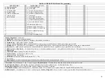
table on next page for programming options effected
by MASTER RESET. NOTE: A power out error
message will be generated when a master reset is
performed. The table outlines the results of using
MASTER RESET.
ITEM RESET
TO
CASH BOX
$0.00
SALES $0.00
NUMBER SOLD
0
SALES PER COLUMN
0
ESCROW OFF
FORCE OFF
SET REGULAR PRICES
99.95
SET HAPPY HOUR PRICES
99.95
LIST ERRORS
Pwr Out
TUBE FILL/DISPENSE
CLEARED
DAYLIGHT SAVINGS
OFF
NOT AVAILABLE
OFF
CREDIT TIMER
OFF
DOOR OPEN
0
POWER OUT
1
IDLE MESSAGE
RESET
ENABLE DOLLAR SIGN
ON
MACHINE NUMBER
UNCHANGED
SET HAPPY HOUR
CLEARED
NOT AVAILABLE TIME
CLEARED
HEALTH CONTROL
OFF
PASSWORD 0000
STS ENABLE
OFF
CUSTOM STS
CLEARED
NOVEND LIMIT
0
SOLD OUT
ENABLED
PRICE DISPLAY
ON
SHELF CONFIG
G
INTERVAL CLEARING
OFF
DISPLAY TEMPERATURE
ON
TEMPERATURE UNITS
DEG F
SERIAL #
UNCHANGED
LOCATION ID
UNCHANGED
CR ASSET #
UNCHANGED
NA ASSET #
UNCHANGED
CM ASSET #
UNCHANGED
SOLD OUT TIMES
CLEARED
DEX PASSWORD
000000
DOOR OPEN TIME
CLEARED
POWER OUT TIME
CURRENT TIME
STORAGE TEMP
57º F (13.8º C)
REFRIG TEMP
37º F (2.7º C)
CONSUMER OVERPAY
OFF
MACHINE NUMBER
-
Press key “1”
(PASSWORD REQUIRED)
Allows assigning a user number to the machine for
audit and/or inventory control requirements. Press
the number “1” on the keypad and “MACHINE
NUMBER” will show across the display and then
change to the number currently assigned to the
machine (i.e. ID 1). Press the “
” key and the
display will read “ID”. Enter the new number
(numeric field, 4 characters maximum). If the new
number is less than 4 characters press the “
” key
after entering it and the display will read “OK”
momentarily and will return to “SETUP MODE”.
Press the “CLR Key to return to “Machine Number”.
Press the “CLR” key to return to “SETUP MODE 1”
or press the “A” key to advance to the next menu
item below.
SET HAPPY HOUR
- Press key “2”
(PASSWORD REQUIRED)
Allows the service technician to turn Happy Hour ON
or OFF. Press the number “2” on the keypad and
“SET HAPPY HOUR” will show across the display.
Happy Hour. Press the
Key and display will show
“Happy Hour: Off (On). Press “
” - turn On (Off).
Press the “CLR Key to return to “Set Happy Hour”.
Press the “CLR” key to return to “SETUP MODE 1”
or press the “A” key to advance to the next menu
item below.
SET NOT AVAIL TIME
- Press key “3”
(PASSWORD REQUIRED)
Password protected. Before entering or changing
this setting you must enter the password if one has
been assigned. This mode allows up to 4 different
time periods that use of the machine may be
restricted. Refer to Initial Set Up section Set Not
Available Times on page 12.
CONSUMER OVERPAY
-
Press key “4”
(PASSWORD REQUIRED)
Allows the service technician to set the machine up
to allow consumer overpay to vend. This will allow a
vend if there is not enough change in the mech to be
paid to consumer. Factory default will be Off. Press
the number “4” key and display will show “Consumer
Overpay”. Press “
” Key and display will show
Summary of Contents for BevMax 4
Page 2: ...1 ...
Page 69: ...68 ...
Page 70: ...69 MACHINE FRONT VIEW 6A 9 11 13 14 5B 5A 7 3A 4B 19 18 6B 3C 4B 4A 2 4C 17 16 1 12 20 ...
Page 72: ...71 CABINET DETAIL PRODUCT AREA 3 2B 12 9 6 7 2A 8 5 14 11 ...
Page 74: ...73 CABINET DETAIL SERVICE DOOR AREA 1 16 10 4 7 11 5 17 11 4 5 20 22 21 14 12 2 10 15 8 ...
Page 78: ...77 DELIVERY PICKER CUP ASSEMBLY 11 1 2 21 10 5 16 14 15 17 4 7 12 13 19 6 19 20 9 8 19 3 22 ...
Page 84: ...83 GATE TRAY DETAIL 8 3 7 11 1 2 4 6 12 13 14 10 9 ...
Page 96: ...95 HARNESSES 8 2 10 1 4 9 3 6 7 11 24 18 17 12 21 16 23 19 20 15 25 26 22 5 ...
Page 98: ...97 ...

