


3
www.cranecpe.com
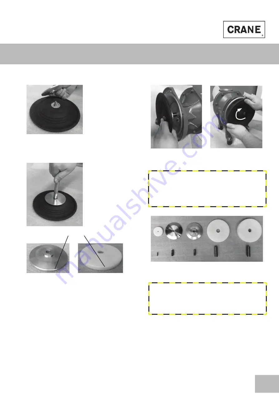
Replacing the diaphragms
Place switch disc on top. The radius or the chamfer is
mounted in the direction of the diaphragm´s air side.
(Pic. 8)
Pic. 8
Screw piston rod onto set screw and tighten by hand
(nopped E4® assembly unit including the piston rod, see
Pic. 9)
Pic. 9
Pic. 10
Before assembling the diaphragm unit, check whether
other parts of the center block need to be exchanged
(e.g. defective or dirty seals, piston rod bearings, defect
air valve, pilot rod or silencer). If required, exchange these
accordingly.
Slide in the nopped E4® assembly unit into the center block
(picture 11) and fix the second diaphragm with switch disc
on the opposite side (mount the threaded pin in the second
nopped E4® diaphragm as shown in picture 7). Tighten the
second diaphragm by hand (picture 12). At the same time,
lock the piston rod with a wrench.
Install pump chambers, insert valve seats and balls (check
for any damages and if required replace), mount suction
and discharge manifolds as per the DEPA® IOM.
Pic. 11
Pic. 12: Tighten by hand
Note:
For installation of DEPA® nopped E4® diaphragms
switch discs and set screws in the matching sizes are needed.
Switch disc material for sizes 15, 50 and 80 is POM, for the
sizes 25 and 40 aluminium. Each switch disc has a different
thickness. The set screws are available in three sizes (15, 25 &
40 and 50 & 80)
Pic. 13: Switch discs and set screws
Note:
For DEPA® pumps with nopped E4® diaphragms a new
pump coding system is used. To recognize a retrofitted DEPA®
pump, please use the sticker enclosed in this manual and
attach it, next to the nameplate area. Upon request we can
supply you with a new nameplate.
Chamfer radius
Aluminium switch disc
POM switch disc
15 25 40 50 80


