D
ESIGN
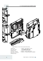
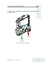
G-13.mft standard/Casino/SGI/BDTA/AMU
16
National Rejectors, Inc. GmbH, Buxtehude
S1
S2
Switching blocks
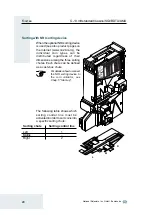
On the rear, the coin validator is equipped with
two switching blocks (6, Fig. 1) with 10 DIL
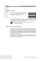
switches S1.1–10 and S2.1–10 each.
The DIL switches have different functions, e.g. inhibit coin channels, select
memory block. For details on how to use the switching blocks to set the
individual functions, see Chap. 6 "Operation".
On the rear of the device you will find a brief description of the
individual switch functions.
Return lever and return button
The return lever (1, Fig. 1a) on the top of the device is operated using the
return button on the machine, if the coins that have already been inserted are
to be returned, or if a jam caused by, e.g., coins that have become stuck
must be removed. Operating the return lever opens the measurement and
validation area of the coin validator so that all objects in the coin validator are
transported into the return area.
Devices with front entry through a front plate do not have a return lever. Here
the measurement and validation area is opened by pressing the return
button (1, Fig. 1b) on the front plate.
Summary of Contents for NRI G-13.mft Standard
Page 2: ......


