T
ECHNICAL
DATA
G-13.mft standard/Casino/SGI/BDTA/AMU
52
National Rejectors, Inc. GmbH, Buxtehude
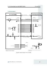
G-13.mft with G-18 BDTA interface – machine
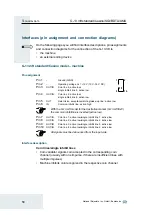
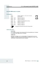
Pin assignment
Pin 1
–
Ground (GND)
Pin 2
–
Operting voltage U
O
= +12 V (10 V–16 V DC)
Pin 3
OUT
String line: active low
Pin 4
OUT/IN
Wake-up line (internal and external): active low
Pin 5
OUT
Return line: active low
Pin 6
IN
Common inhibit line: active high
Pin 7
OUT
Coin line 4: active low
Pin 8
OUT
Coin line 7: active low
Pin 9
OUT
Coin line 6: active low
Pin 10
OUT
Coin line 2: active low
Pin 11
OUT
Coin line 5: active low
Pin 12
OUT
Coin line 3: active low
Pin 13
OUT
Coin line 1: active low
Pin 14
OUT
Coin line 8: active low
All signals must be debounced from the input side.
Interface description
Coin lines
Coin validator signals coin accepted in the corresponding coin channel
(usually with one impulse, if there are insufficient lines with multiple
impulses)
Return line
After the return button has been pressed, the coin validator signals the
opening of the measurement and validation area
Common inhibit line
Machine inhibits coin acceptance
Wake-up line
•
Coin validator wakes up machine, after being woken up by coin
insertion, and remains active, until inserted coin has been processed
(internal waking up)
•
Machine wakes up coin validator (active until inserted coin has been
processed) (external waking up)
String line
Coin validator signals manipulation attempt, e.g., a coin pulled back by a
string, and inhibits coin acceptance for 30 seconds
1
2
14
13
Summary of Contents for NRI G-13.mft Standard
Page 2: ......


