T
ECHNICAL
DATA
G-13.mft standard/Casino/SGI/BDTA/AMU
56
National Rejectors, Inc. GmbH, Buxtehude
G-13.mft AMU model – machine
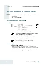
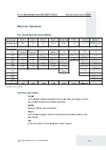
Pin assignment
Pin 1
–
Operating voltage U
O
= +12 V (10 V–16 V DC)
Pin 2
–
Ground (GND)
Pin 3
OUT
Coin line 5: active low
Pin 4
OUT
Coin line 6: active low
Pin 5
OUT
Coin line 7: active low
Pin 6
IN
Inhibit line: active high (internal pull-up)
Pin 7
OUT
Coin line 1: active low
Pin 8
OUT
Coin line 2: active low
Pin 9
OUT
Coin line 3: active low
Pin 10
OUT
Coin line 4: active low
All signals must be debounced from the input side.
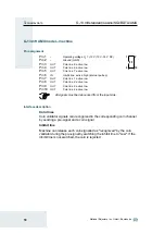
Interface description
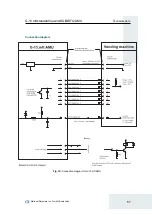
Coin lines
Coin validator signals coin recognized in the corresponding coin channel
by sending a pre-signal and a coin signal
Inhibit line
Machine can release each coin signalled as "recognized" by the coin
validator during the pre-signal by switching the inhibit line to "Low". If the
inhibit line is not switched, the coin is rejected
1
2
10
9
Summary of Contents for NRI G-13.mft Standard
Page 2: ......


