G-13.mft standard/Casino/SGI/BDTA/AMU
G
LOSSARY
69
National Rejectors, Inc. GmbH, Buxtehude
ECV
Electronic Coin Validator
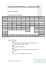
G-18 interface
14-pole
→
BDTA interface, taken over from the NRI coin
validator G-18.mft for battery applications in the tobacco
vending sector.
G-40 interface
16-pole
→
BDTA interface, taken over from the NRI coin
validator G-40.5000 for mains applications in the tobacco
vending sector.
Impulse length
→
Coin impulse length
Impulse number
→
Coin impulse number
Inhibit signal line
With the AMU model the machine control system uses the
inhibit signal line to inhibit each of the coins inserted during
acceptance operation (after the coin has been measured
and before the coin will pass the accepted coin sensors). The
coin inserted will not be accepted.
→
Single inhibit signal line
→
Common inhibit signal line
Memory block
Memory of the coin validator. At the manufacturer’s company,
a customer-specific setting is programmed to determine
whether the 32
→
coin channels of the G-13.mft are to be
data-managed in one memory block (single block data-
management) or, when divided into 16 channels each, in two
memory blocks (double block data-management). Two
(memory) blocks 0 and 1 can be used to data-manage two
independent configurations of coin/device data (e.g. two
currencies). However, for coin validator operation, only one
memory block with 16 channels can be active at a time; the
other block is inhibited.
The memory block(s) can be updated using WinEMP or (
→
data block download).
Return signal line
When operating the return lever/button on the coin validator,
a return signal is transmitted to the return signal line (not with
AMU model). The coin validator then releases all the coins
and foreign bodies inside the device.
The return signal line can also be used to transmit a sorting
signal or a coin acceptance signal (only for Casino model,
instead of
→
accepted coin sensors).
Summary of Contents for NRI G-13.mft Standard
Page 2: ......


