background image

M118.x 

5 of 11 


15.


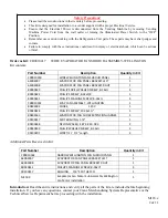
Remove the old Evaporator Fan Shroud Assembly and discard. 
 

Installation of the New Fan Shroud Assembly: 
          Note: 
For Build-Up of the Narrow Fan Shroud Assembly go to Page 7. 


16.


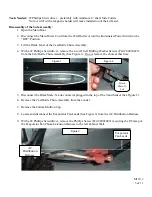
Lay the New Fan Assembly in front of the vender (Figure 7). 


17.


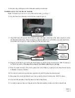
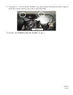
Align the Female Evaporator Fan Choke Extension Harness connectors to the male connectors of the 
AC Distribution Harness.  When connecting, align the ribbed wire with white wire and smooth wire 
with black wire (Figure 8). Ensure nothing is in the fan blade area. 


18.


Plug the end of the Power Cord to the Wall Outlet (or turn the Power Switch to the “ON” Position) to 
test the fan assembly.  

Warning:


Do not touch Fan Blades while they are moving.


19.


Press the metal Actuator of the Tri-Teq Receiver in the Cabinet, or pull out on the Door Switch by the 
T-Handle of Generic Venders. 


20.


The fan will start slowly and increase speed slowly until it reaches maximum speed.  


21.


Disconnect the end of the Main Power Cord or turn the Power Switch to the “OFF” Position. 


22.


Clean all dirt and debris from the bottom of the Cabinet Tank.  


23.


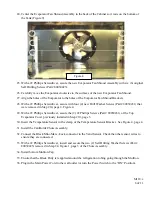
Carefully maneuver the new Evaporator Fan Shroud Assembly in the rear of the Cabinet Tank. 


Note: 

Ribbed Wire 

to White Wire 

Figure 8


Note: 

Smooth Wire 

to Black Wire 

Figure 7


Summary of Contents for P Series

Page 1: ...stallation page 2 Narrow P Series Fan Shroud Assembly Build up page 7 Evaporator Fan Replacement Conversion Chart page 10 Models affected All Domestic P Series Model Venders Produced Beginning Production Run 6925CB and higher Reason To Provide Step by Step Instructions for the removal of the original Evaporator Fan Shroud Assembly and installation of the new Evaporator Fan Shroud Assembly with the...

Page 2: ...ORATOR FAN PANEL BRACKET RGHT 1 80030431 PHILLIPS MACHINE SCREW 8 18x 4 90190217 BUSHING 3 4 SPLIT HEYCO 1 M118 0 Evaporator Fan Motor Sub Assembly Wellington Fan Motor Installation 1 Introduction Read the entire instructions and verify all the parts of the kit are included before beginning installation If you have any questions contact your Crane Merchandising Systems Representative or the Techni...

Page 3: ...rilling Washer Screws Part 80030423 from the Can Bottle Chute Assembly See Figure 1 Do not remove the chute at this time 5 Disconnect the Black Mate N Lok connector plugged in the top of the Vend Sensor See Figure 2 6 Remove the Can Bottle Chute Assembly from the vender 7 Remove the bottom Mullion Cap 8 Locate and disconnect the Evaporator Fan Leads See Figure 3 from the AC Distribution Harness 9 ...

Page 4: ...iver remove the Phillips Screws Part 80030431 securing the Evaporator See Figure 4 marked B to the fan shroud 13 Carefully move the Evaporator Assembly Counter clockwise and allow to rest in front of the Condenser Figure 5 Be careful not to kink or bend the refrigeration tubing Do not drop 14 With a 2 Phillips Screwdriver remove the Self Drilling Washer Screws Part 80030423 marked C in Figure 6 fr...

Page 5: ...the end of the Power Cord to the Wall Outlet or turn the Power Switch to the ON Position to test the fan assembly Warning Do not touch Fan Blades while they are moving 19 Press the metal Actuator of the Tri Teq Receiver in the Cabinet or pull out on the Door Switch by the T Handle of Generic Venders 20 The fan will start slowly and increase speed slowly until it reaches maximum speed 21 Disconnect...

Page 6: ... 2 Phillips Screwdriver secure the 2 2 Phillips Screws Part 80030431 of the Top Evaporator Cover previously installed in Step 10 page 3 30 Insert the Temperature Sensor in the clamp of the Temperature Sensor Bracket See Figure 4 page 4 31 Install the Can Bottle Chute Assembly 32 Connect the Black Mini Mate Lock connector to the Vend Sensor Check the other sensor wires to ensure they are connected ...

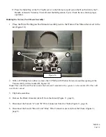
Page 7: ... the kit Figure 10 2 With a 2 Phillips Screwdriver remove the 2 Phillip with Washer Screws around the opening of the Fan Assembly circles marked D Figure 10 Note There are Plastic Washers under the bottom 2 marked with a square circles marked E They will need to be reused 3 Flip both assemblies 4 Remove the Black Grommet item F from the shroud Figure 11 page 8 5 Disconnect the Female A and B Wire ...

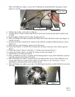
Page 8: ...oud 14 Connect the Female A and B Wire Connectors to the Male Connectors of the Choke Figure 10 page 6 15 Connect the Female Brown to the Male C Position of the Choke Figure 11 16 Connect the Female Blue to the Male D Position of the Choke Figure 11 17 Flip the Narrow Fan Shroud Assembly 18 With a 2 Phillips Screwdriver install the 2 Self Drilling Washer Screws Part 80030423 in the Fan Assembly do...

Page 9: ...g the 2 7 Wire Ties Part 90190201 route the Evaporator Fan Harness as shown in Figure 13 and secure as shown Trim the excess of the tie using Side Cutters 22 Continue with Installation of the New Assembly on page 5 Figure 13 ...

Page 10: ...e 4 Petals Plastic A CR0010417 80450128011 9 8 Blade 7 Petals Plastic prior to run 7772 D 80450128011 80450148001 9 29 Implemented in Production Effective run 7772 Blade 5 Petals B CR0010417 80450154001 9 29 Blade 5 Petals Metal C CR0010417 CR0010331 9 29 Ribs Blade 5 Alluminum 8 30 CW Wellington F CR0010331 E Series Evaporator Fans Part Number Bolt Pattern Diameter Notes Type Replacement 49100020...

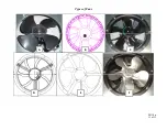
Page 11: ...M118 x 11 of 11 Types of Fans A B C D E F ...

Reviews: