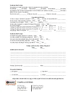
background image

Submersible Pumps

Resistance of cable and pump motor (measured at pump control):
Red-Black:_______Ohms(

Ω

)      Red-White:_______Ohms(

Ω

)     White-Black:_______Ohms(

Ω

)

Resistance of Ground Circuit between Control Panel and outside of pump: __________Ohms(

Ω

)

MEG Ohms check of insulation:
Red to Ground:  _________  White to Ground:  __________   Black to Ground: ____________
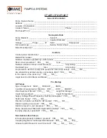
Operational Checks

Is there noise or vibration present?   YES___   NO___  Source of noise/vibration: ___________
Does check valve operate properly?   YES___   NO___   N/A___
Is system free of leaks?   YES___   NO___    

Leaks at: ______________________________

Does system appear to operate at design 

fl

 ow rate?   YES___   NO___

Nominal Voltage: _____________________ Phase:     1Ø     3Ø     (select one)
Voltage Reading at panel connection, Pump OFF: L1, L2  _____   L2, L3  ____   L1, L3 _____
Voltage Reading at panel connection, Pump ON: L1, L2  ______  L2, L3  ____   L1, L3 _____
Amperage Draw, Pump ON:   L1 ____________  

L2  _____________  

L3 _____________

Submersible Pumps

Are BAF and guide rails level / plumb?   YES___   NO___
Is pump seated on discharge properly?   YES___   NO___
Are level controls installed away from turbulence?   YES___   NO___
Is level control operating properly?   YES___   NO___ 


Is pump fully submerged during operation?   YES___   NO___

Follow up/Corrective Action Required

YES___          NO___

Additional Comments:

____________________________________________________________________________
____________________________________________________________________________
____________________________________________________________________________
____________________________________________________________________________
____________________________________________________________________________
____________________________________________________________________________
____________________________________________________________________________

Startup performed by: _____________________   Date: ______________________________

Present at Start-Up

(  ) Engineer: ____________________________   (  ) Operator: ________________________

(  ) Contactor: ____________________________   (  ) Other: ___________________________

All parties should retain a copy of this report for future trouble shooting/reference

A Crane Co. Company

420 Third Street 

83 West Drive, Brampton

Piqua, Ohio 45356 

Ontario, Canada L6T 2J6

Phone: (937) 778-8947 

Phone: (905) 457-6223

Fax: (937) 773-7157 

Fax: (905) 457-2650

www.cranepumps.com

Summary of Contents for Weinman B Series

Page 1: ... product changes may occur As such Crane Pumps Systems reserves the right to change product without prior written notification 420 Third Street 83 West Drive Bramton Piqua Ohio 45356 Ontario Canada L6T 2J6 Phone 937 778 8947 Phone 905 457 6223 Fax 937 773 7157 Fax 905 457 2650 www cranepumps com Form No 119980 Rev E Series B VB VBM Type VB Vertical Pump Type VBM Vertical Frame Mounted Pump Type B ...

Page 2: ...discharge openings DO NOT insert fingers in pump with power connected Always wear eye protection when working on pumps Make sure lifting handles are securely fastened each time before lifting DO NOT operate pump without safety devices in place Always replace safety devices that have been removed during service or repair Secure the pump in its operating position so it can not tip over fall or slide...

Page 3: ...e Center check your Weinman representative or Crane Pumps Systems Inc Service Department in Piqua Ohio telephone 937 778 8947 or Crane Pumps Systems Canada Inc Bramton Ontario 905 457 6223 B INSTALLATION 1 FOUNDATION The pump foundation should be sufficiently substantial to form a level rigid support for the combined weight of the pump and driver and maintain alignment of the installed unit Founda...

Page 4: ...nment when the straight edge rests evenly on the coupling rim at all positions Allowance may be necessary for temperature changes and for coupling halves that are not of the same outside diameter Care must be taken to have the straight edge parallel to the axis of the shafts Correction for Angular and Parallel Misalignment is made by adjusting the shims under the driver After each change it is nec...

Page 5: ...on arrow on the pump casing Separate the coupling halves then start motor to see that it rotates in the direction required by the pump If it does not reverse any two main leads of the 3 phase wiring to the motor The coupling halves can be reconnected and the pump primed for starting C OPERATION 1 PRIMING CAUTION Before starting the pump the casing and suction line must be filled with liquid and ai...

Page 6: ... Heat exchanger is required for higher liquid temperatures 3 Pumps with seal chamber may be pressurized with Shell Alvania EPRO 71030 grease through suitable grease fitting if liquid lubrication is not available 2 IMPELLER ADJUSTMENT An outstanding feature of this pump is the axial adjustment of the impeller to compensate for eventual wear or corrosion Correct impeller adjustment will insure optim...

Page 7: ...rox 1 8 wide cut a groove axially along the sleeve to the shoulder of the shaft Grind the groove as deep as possible without damaging the shaft 2 After the groove has been cut insert a wedge tipped cold chisel into the groove at the impeller end of the sleeve Support shaft on a V block under the sleeve Tap chisel sharply with a hammer until crack occurs along the base of the groove 3 Pry groove ap...

Page 8: ...y light oil to the inside of the seal bellow and shaft sleeve 14 and slide the rotating seat assembly 89B onto the shaft sleeve 3 Place packing box cover 11 against frame 19 Be sure register is aligned and flange is fully seated in power frame and in proper position Then attach seal gland 251 to packing box cover with belts and nuts 209 210 Tighten securely Seal may be tested for leakage by applyi...

Page 9: ...ase 57 Elbow Suction 59 Cover Handhole 69 Lockwasher Bearing 73 Gasket Casing 203 Plate Name 204 Locknut Adjusting 206 Clip Split Gland 207 Fitting Grease 208 Plug Pipe 209 Bolt Machine 210 Nut Hex 211 Screw Set 212 Screw Cap 213 Screw Cap 214 Screw Drive Nameplate 215 Screw Cap 216 Plug Pipe 217 O ring ITEM DESCRITION 218 Screw Cap 220 O ring 221 Screw Cap 223 Cover Handhole 224 Screw Cap 226 Scr...

Page 10: ...e 40 Deflector 46 Key Coupling ITEM DESCRITION 51 Retainer Grease 59 Cover Handhole 69 Lockwasher Bearing 73 Gasket Casing 195 Screw Set 203 Plate Name 204 Locknut Adjusting 206 Clip Split Gland 207 Fitting Grease 208 Plug Pipe 209 Bolt Machine 210 Nut Hex 211 Screw Set 212 Screw Cap 213 Screw Cap 214 Screw Drive Nameplate 215 Screw Cap 216 Plug Pipe 217 O ring 218 Screw Cap 236 Plug Pipe ITEM DES...

Page 11: ...tboard 51 Retainer Grease 53 Base 57 Elbow Suction 59 Cover Handhole 69 Lockwasher Bearing 73 Gasket Casing 203 Plate Name 204 Locknut Adjusting 206 Clip Split Gland 207 Fitting Grease 208 Plug Pipe 209 Bolt Machine 210 Nut Hex 211 Screw Set 213 Screw Cap 214 Screw Drive Nameplate 215 Screw Cap 216 Plug Pipe 217 O ring 218 Screw Cap 220 O ring 221 Screw Cap 223 Cover Handhole ITEM DESCRITION 224 S...

Page 12: ...formance specifications must be in writing and such writing must be signed by our authorized representative Due to inaccuracies in field testing if a conflict arises between the results of field testing conducted by or for user and laboratory tests corrected for field performance the latter shall control RECOMMENDATIONS FOR SPECIAL APPLICATIONS OR THOSE RESULTING FROM SYSTEMS ANALYSES AND EVALUATI...

Page 13: ...nt To Insure That Employees Will Not Be Exposed To Health Hazards In Handling Said Material All Applicable Laws And Regulations Shall Apply IMPORTANT WARRANTY REGISTRATION Your product is covered by the enclosed Warranty To complete the Warranty Registration Form go to http www cranepumps com ProductRegistration If you have a claim under the provision of the warranty contact your local Crane Pumps...

Page 14: ...__ Type _________________________________ Number and size of short circuit device s ___________ Amp rating ___________________ Overload Type _____________ Size ______________ Amp rating ___________________ Do protection devices comply with pump and motor Amp rating YES___ NO___ Are all electrical and panel entry connections tight YES___ NO___ Is the interior of the panel dry YES___ NO___ Liquid le...

Page 15: ...s installed away from turbulence YES___ NO___ Is level control operating properly YES___ NO___ Is pump fully submerged during operation YES___ NO___ Follow up Corrective Action Required YES___ NO___ Additional Comments ____________________________________________________________________________ ____________________________________________________________________________ ___________________________...

Page 16: ...Notes ...

Reviews: