


3
A - GENERAL INFORMATION
TO THE PURCHASER
Congratulations! You are the owner of one of the
fi
nest
pumps on the market today. These pumps are products
engineered and manufactured of high quality components.
With years of pump building experience along with a con-
tinuing quality assurance program combine to produce a
pump which will stand up to the toughest applications.
Check local codes and requirements before installation.
Servicing should be performed by knowledgeable pump
service contractors or authorized service stations.
RECEIVING
Upon receiving the pump, it should be inspected for dam-
age or shortages. If damage has occurred,
fi
le a claim
immediately with the company that delivered the pump.
If the manual is removed from the crating, do not lose or
misplace.
STORAGE
Short Term -
Pumps are manufactured for ef
fi
cient
performance following long inoperative periods in storage.
For best results, pumps can be retained in storage, as
factory assembled, in a dry atmosphere with constant
temperatures for up to six (6) months.
Long Term -
Any length of time exceeding six (6) months,
but not more than twenty four (24) months. The units
should be stored in a temperature controlled area, a roofed
over walled enclosure that provides protection from the
elements (rain, snow, wind blown dust, etc..), and whose
temperature can be maintained b40 deg. F and
+120 deg. F. Pump should be stored in its original shipping
container and before initial start up, rotate impeller by hand
to assure seal and impeller rotate freely.
SERVICE CENTERS
For the location of the nearest Weinman Service Center,
check your Weinman representative or Crane Pumps &
Systems, Inc., Service Department in Piqua, Ohio, telephone
(937) 778-8947 or Crane Pumps & Systems Canada, Inc.,
Bramton, Ontario, (905) 457-6223.
B- INSTALLATION
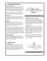
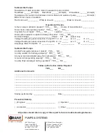
1. FOUNDATION
The pump foundation should be suf
fi
ciently substantial
to form a level, rigid support for the combined weight
of the pump and driver and maintain alignment of the
installed unit. Foundation bolts, of the proper size, should
be imbedded in the concrete. A pipe sleeve, about 2½”
diameters larger than the bolt, should be used to allow for
fi
nal positioning of the bolts. See Figure 1.
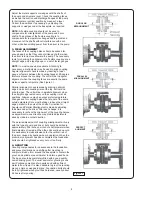
2. MOUNTING - Type VB and VBM:
Position the unit on the foundaton and level the pump
base, using metal shims, so that the pump shaft is in
vertical alignment and the pump suction and discharge
fl
anges are level in both vertical and horizontal plane. Base
may be grouted following alignment. Use a plumb line from
fl
oor above to establish centerline of pump and
fl
exible
drive shaft and bearings.
Type B Units:
Pumps and drivers that are received from the factory
with both machines mounted on a common baseplate,
were accurately aligned before shipment. All baseplates
are
fl
exible to some extent and, therefore, must not be
relied upon to maintain the factory alignment. Preliminary
alignment is necessary after the complete unit has been
leveled on the foundation, and again, after the unit is
piped, and rechecked periodically as outlined in the
following paragraphs.
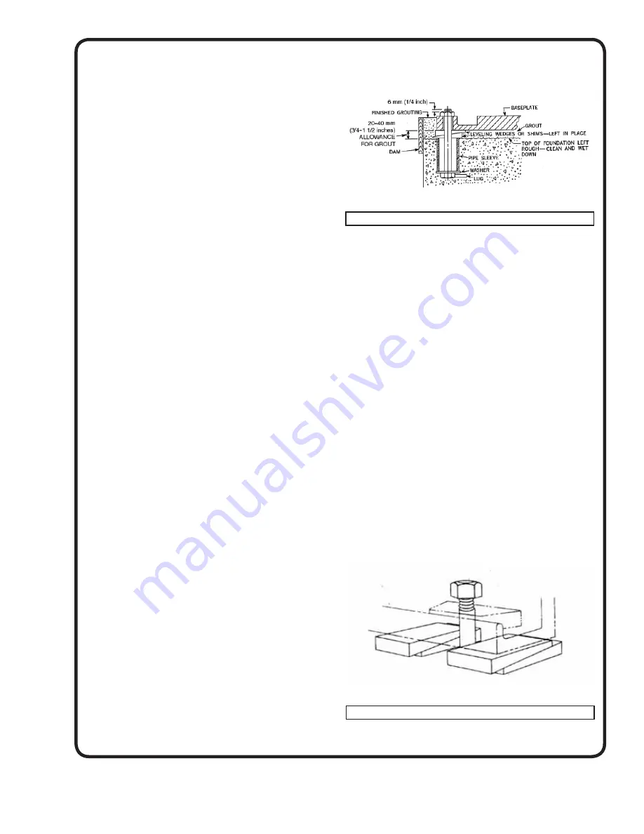
Position unit on foundation and level the baseplate,
using rectangular metal blocks and shims, or wedges
having a small taper as shown in Figure 2. A gap of 3/4”
to 1½” should be allowed between the baseplate and
foundation for grouting.
Figure 1. Foundation Bolt Location and Anchorage
Figure 2. Adjusting Wedges for Mounting
Summary of Contents for Weinman B Series
Page 16: ...Notes ...


