


6
D. MAINTENANCE
1. LUBRICATION
The pump and its component parts that require lubrication
have been lubricated at the factory, except for bearings
that are oil lubricated. Oil reservoir must be
fi
lled before
start up. (See below)
Subsequent lubrication depends on operating conditions.
Periodic inspection of bearing lubrication is necessary and
additional grease or oil should be added as required.
CAUTION: DO NOT overgrease bearings or add
excess oil.
The following lubricants are recommended:
Grease lubricated ball bearings: Shell Alvania #71012 or
equal.
Oil lubricated ball bearings: SAE #10 non-detergent type
oil.
Packing boxes: Lithium base grease. Shell Alvania
#71012 or equal.
Double seal: Pressurized water or light oil circulated
through seal chamber. See below for recommended
lubrication.
Driver: See Manufacturers recommendations for proper
lubrication.
NOTE:
Under normal conditions, a ball bearing will run
10
0
F to 60
0
F above surrounding temperatures. If bearing
temperature becomes extremely hot, check for improper
lubrication, such as over-greasing, wear, incorrect pump
alignment, etc.
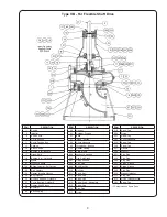
SERIES B ONLY:
To
fi
ll the oil reservoir in the frame (19)
1. Install the TRICO OPTO-MATIC CONSTANT LEVEL
OILER (77) on the frame. Unscrew the plastic bottle
from the oiler and remove breather (235) from the
frame.
2. Fill the bottle of the oiler and screw it onto the lower
reservoir.
Several
fi
llings of the bottle will be required
before the oil level in the bearing reservoir is equal
to the level for which the oiler is adjusted.
NEVER
fi
ll
the frame reservoir through the lower reservoir of the
oiler or re
fi
ll bottle while pump is operating.
3. When proper oil level is obtained, re
fi
ll and replace the
plastic bottle on the oiler and replace the breather
(235) in the frame.
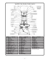
DOUBLE SEAL LUBRICATION
The seal chamber of the packing box cover (11) must be
pressurized with a clear liquid to cool and lubricate the
seal faces. Liquid should be circulated through the seal
chamber at a pressure equal to or 15 to 20 psi above
maximum pressure at the pump discharge.
Recommended lubrication systems are as follows:
1. Water from an outside source, such as a water seal
system or light oil from a pressurized system.
2. Liquid from the pump casing (1) through a suitable
fi
lter if liquid is not over 180°F. Heat exchanger is
required for higher liquid temperatures.
3. Pumps with seal chamber may be pressurized with
Shell Alvania EPRO #71030 grease through suitable
grease
fi
tting if liquid lubrication is not available.
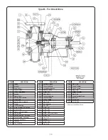
2. IMPELLER ADJUSTMENT
An outstanding feature of this pump is the axial
adjustment of the impeller to compensate for eventual
wear or corrosion. Correct impeller adjustment will insure
optimum operating performance and ef
fi
ciencies.
To adjust impeller clearance:
a. Disconnect power supply to the driver at the starter.
b. Loosen the three lock nuts and jack screws (204
and 286), then tighten the three cap screws (213)
evenly until the impeller just rubs the suction cover
(9) when the shaft is rotated by hand. It may be
necessary to bump the shaft lightly on the coupling
end to make sure impeller is against the suction cover.
c. Tighten the jack screws (286),
fi
nger tight, against
the power frame (19); then loosen cap screws (213).
d. Tighten the jack screws an additional 1/3 turn
(2 hex) to obtain .016” to .020” impeller clearance.
The clearance may be measured with feeler
gauge through suction inlet of the suction cover.
e. Carefully tighten cap screws (213) and lock nuts
(204), then rotate shaft by hand to make certain that
impeller does not rub against suction cover. Place
pump in operation and check power draw to make
certain impeller does not rub casing.
3. PACKING BOX CARE
Pumps are normally furnished with grease
fi
ttings (243) for
packing lubrication, unless purchased otherwise.
When installing new rings of packing, clean packing box
(11) and inspect parts for any damage. If the shaft sleeve
(14) is worn or grooved, it should be replaced. New packing
will not provide adequate sealing on a worn shaft sleeve.
Insert two new rings of packing in front of lantern ring.
Stagger joints to minimize leakage. Tamp each ring in
place. Rotate shaft several times after tamping each ring.
Replace lantern ring. Add three rings of packing behind
lantern ring. Replace gland (17) and bolts (209) and nuts
(210), rotate shaft and tighten gland securely. Be sure
lantern ring is positioned to receive lubrication through item
(243). After rotating shaft several turns, loosen nuts (210) to
fi
nger
fi
ght for starting.
IMPORTANT:
The liquid being pumped should slowly
and constantly drip through the packing and gland. This
prevents overheating, high power consumption and sleeve
damage. Lubricate through grease
fi
tting (243) or by
removal of
fi
tting and substituting tubing and an outside
source of water or oil.
Summary of Contents for Weinman B Series
Page 16: ...Notes ...


