8
c. Insert shaft assembly into the frame from the
coupling end until the space between the
fl
ange
of the bearing housing at end of the frame is
approximately 5/16”. Replace cap screws (213)
fi
nger-tight.
d. Place bearing lock washer (69) on the shaft and
thread bearing lock nut (22) tight against the lock
washer. Bend tangs of the washer into the lock
nut when tight.
e. Press shaft seal (49) into the bearing cover (37)
with lip of the seal extending toward the coupling.
Position bearing cover over the bearing housing
(33) and replace and tighten cap screws (332),
also replace jack screws with nuts (286 and 204),
but do not tighten.
SHAFT SLEEVE (14)
1. After old sleeve has been removed, clean shaft
with emery cloth and wipe thoroughy to remove
metal particles, also wipe inside of new sleeve to
be sure that it is clean.
2. Note that the new shaft sleeve is chamfered on
one end. This end will be installed against the
shoulder of the shaft (6).
3. Place the shaft sleeve in a preheated oven set at
650
0
F for 1-1/2 hours to allow sleeve to heat
uniformly and expand.
4. Place shaft in a vertical position in a vise, impeller
end upward. Remove shaft sleeve from the oven
and drop sleeve, chamfered end
fi
rst, over the
shaft; making certain that the end of the sleeve is
seated against the shaft shoulder.
5.
NOTE:
This operation must be done rapidly
without allowing the shaft sleeve to cool. Do not
allow the sleeve to stop before it is properly seated.
Hold Shaft sleeve snug against the shaft shoulder
until shrink begins. Allow the sleeve to cool below
100
0
F before proceeding with pump assembly.
6.
Replace
de
fl
ector (40) according to original
location.
PACKING BOX COVER (11) ASSEMBLY
a. To install new packing see Section D, Paragrah 3.
Position packing box cover against frame (19)
Be sure registered
fl
ange is fully-seated in power
frame.
b. To install mechanical shaft seal, clean and
inspect all parts and remove all burrs, nicks, etc.
from shaft and sleeve.
CAUTION:
Protect the
lapped faces of the seal during installation.
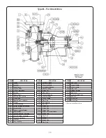
WITH TYPE 1 CRANE DOUBLE SEAL
1. Apply light oil to the outer surface of the
stationary seal seats and O-rings (89A) and press
one seal seat into the seal gland (251), and the
other seal seat into the packing box cover (11).
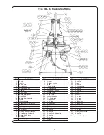
Slide seal gland and gand gasket (259) onto the
shaft. (See Drawing).
2. Apply light oil to the inside of the seal bellow and
shaft sleeve (14) and slide the rotating seat
assembly (89B) onto the shaft sleeve.
3. Place packing box cover (11) against frame
(19). Be sure register is aligned and
fl
ange is
fully seated in power frame and in proper position.
Then attach seal gland (251) to packing box
cover with belts and nuts (209-210). Tighten
securely. Seal may be tested for leakage by
applying 20 pounds of water ressure to the seal
cavity of packing box cover.
IMPELLER (2)
(Replace impeller ring (8), if furnished, before mounting the
impeller).
a. Place impeller key (32) in shalt keyway and
sleeve gasket (38) against shaft sleeve (14) or on
the impeller hub.
b. Spread a drop of Loctite #601 on shaft and
mount impeller (2) on the shaft. Block coupling
end of the shaft, then lay a block of wood over the
suction inlet of the impeller and tap lightly on the
block until impeller is seated.
c. Assemble the impeller screw O-ring (272),
impeller washer (270) and the impeller screw
gasket (28) onto the impeller screw (26). Apply a
drop of Loctite #601 to the impeller screw and
mount the assembly on the end of the pump
shaft.
Tighten
securely.
d. Place casing gasket (73) on packing box cover
fl
ange and mount casing (1) on frame assembly,
then replace cap screws (212).
NOTE:
Casing (1), packing box cover (11) and power
frame must be correctly aligned when reassembled. Be
sure registered
fl
ange of packing box cover is fully seated
in power frame and that casing is aligned and fully-seated
on packing box cover before tightening cap screws (212).
e. Place suction cover gasket (73) on suction cover
(9) and mount suction cover on casing, replacing
cap screws (215). Replace suction cover wear
ring (25), if required, before mounting suction
cover as above.
WEAR RINGS (8 and 25)
a. Suction Cover Ring (25). Remove all rust, scale
and dirt from ring seat. Place new ring into the
suction cover recess, aligning mounting holes
Insert and tighten machine screws (343), which
must
be
fl
ush with the surface of the ring when
seated. Use new machine screws when replacing
ring.
b. Impeller Ring (8). Remove all rust, scale and dirt
from impeller ring seat. Press new ring onto
the impeler, making certain that it is fully seated
on the impeller. Drill and tap new holes for the
ring set screws and install the set screws.
FINAL ASSEMBLY
a. Reassembly pump on the base or base plate.
Mount driver and reassembly coupling. Replace
any tubing or piping required.
b. Adjust impeller clearance per Section D, part 2,
and place pump in operation per Section C.
Summary of Contents for Weinman B Series
Page 16: ...Notes ...


