Procedure
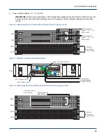
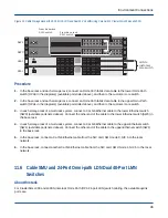
1. In the base rack and each storage rack, connect an OPA fabric data cable to the lower Omni-Path switch
(OPA0 in the diagrams) (available ports listed above), and then to the customer core switch.
2. In the base rack and each storage rack, connect an OPA fabric data cable to the upper Omni-Path switch
(OPA1 in the diagrams) (available ports listed above), and then to the customer core switch.
3. In each storage rack of a multi-rack system, connect a Cat 5/6 Ethernet cable to the lower Ethernet switch
(SW0) (available ports listed above). Connect the other end of the cable to the lower Ethernet switch (SW0) in
the base rack.
4. In each storage rack of a multi-rack system, connect a Cat 5/6 Ethernet cable to the upper Ethernet switch
(SW1) (available ports listed above). Connect the other end of the cable to the upper Ethernet switch (SW1)
in the base rack.
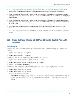
5. In the base rack, connect a Cat 5/6 Ethernet cable from the NIC card, SMU node 0, NIC 5 to the local
network.
6. In the base rack, connect another Cat 5/6 Ethernet cable from the NIC card, SMU node 1, NIC 5 to the local
network.
11.7 Cable SMU and Omni-path 48-Port LDN with Dual 24-Port LMN
Switches
About this task
For ClusterStor L300 and L300N inter-rack Omni-Path (OPA) 48-port LDN switch cabling, the available uplink
ports are:
●
Upper switch 1 (OPA1) - 17 through 48
●
Lower switch 0 (OPA0) - 17 through 48
For inter-rack LMN switch cabling, the available uplink ports are:
●
Upper switch 1 (SW1) - 5, 7, 17, and 19
●
Lower switch 0 (SW0) - 5, 7, 17, and 19
●
Port 13 is the ISL and is not available.
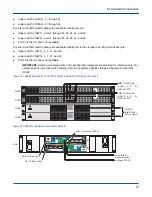
IMPORTANT: Switch port assignments in the configuration diagrams are provided for reference only. For
system-specific inter-rack switch cabling, refer to the system-specific storage configuration document
(SCD).
Environment Connections
48


