System Interconnect Diagram
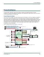
The figure shows the CS-Storm 500GT server interconnect and cable connections between each of the major
subsystem components.
Figure 8. Balanced PCIe 4PLX Interconnect Diagram - CS-Storm 500GT
PSU
PSU
PSU
PSU
PLX
PLX
PLX
PLX
GPU 0
GPU 1
GPU 2
GPU 3
GPU 6
GPU 7
GPU 8
GPU 9
GPU 5/PCIe x16
GPU 4/PCIe x16
PCIe
Switch
Board
Front
Control P
anel
Power
Backplane
PCIe Switch
Board
Front Panel
MDC
MDC
IFB
SMBus
I2C Bus
PMBus
Motherboard
Slot 4
Slot 3
Slot 2
Slot 1
Bridge
Mini-SAS HD
Fan
VGA
CPU 2
CPU 1
Fixed Internal
Drives
PCIe x16*
PCIe x16*
PCIe x16*
PCIe x16*
PCIe x16* Bridge Board
I2C Control
I2C Bus (101644500)
I2C Control (101781600)
USB (101677701)
Fan Control (
101644401)
SATA x4
NVME x4
NVME x4
SATA x4
SATA x4
SATA x4
Drive Bays 0-3
(SATA)
Drive Bays 4-7
(SATA/NVMe)
12V Power (101701301)
12V (101677301)
12V (101677301)
I2C Control signal|Power mgt bus (101677501)
12V
12V
Front Control/Indicators (101782100)
(101644100)
(101701300)
(101781700)
(101782000)
* To PCIe switch board
System Interconnect Diagram
H-6150 (Rev C)
19


