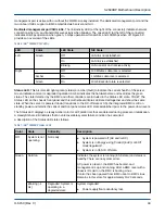
Color
State
Criticality
Description
although still
functional, or system is
operating in a
redundant state but
with an impending
failure warning.
●
Fan warning or failure when the number of fully
operational fans is less than minimum number needed
to cool the system
●
Non-critical threshold crossed (temperature, voltage,
power)
●
Power supply failure
●
Unable to use all installed memory
●
Correctable memory errors beyond threshold
●
Battery failure
●
Error during BMC operation
●
BMC watchdog has reset the BMC
●
Power Unit sensor offset for configuration error is
asserted
●
HDD HSC is off-line or degraded
Amber
Solid on
Critical, non-
recoverable - system is
halted
Fatal alarm: System has failed or shutdown
Blinking (~1
Hz)
Non-critical: System is
operating in a
degraded state with an
impending failure
warning, although still
functioning.
Non-fatal alarm: System failure likely
●
Critical threshold crossed (temperature, voltage, power)
●
VRD Hot asserted
●
Minimum number of fans to cool the system not present
or failed
●
Hard drive fault
●
Insufficient power from PSUs
1.
The overall power consumption of the system is referred to as System Power States. There are a total of six
different power states ranging from: S0 (the system is completely powered ON and fully operational), to S5 (the
system is completely powered OFF), and the states (S1, S2, S3, and S4) referred to as sleeping states.
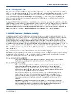
Chassis ID LED. This blue LED is used to visually identify a specific motherboard/server installed in the rack or
among several racks of servers. The ID button on front of the server/node toggles the state of the chassis ID LED.
There is no precedence or lock-out mechanism for the control sources. When a new request arrives, all previous
requests are terminated. For example, if the chassis ID LED is blinking and the ID button is pressed, then the ID
LED changes to solid on. If the button is pressed again with no intervening commands, the ID LED turns off.
Table 8. Intel
®
S2600BP ID LED
LED State
State
On (steady)
The LED has a solid On state when it is activated through the ID button. It remains lit until
the button is pushed again or until an
ipmitool chassis identify
command is
received to change the state of the LED.
Blink (~1 Hz)
The LED blinks after it is activated through a command.
S2600BP Motherboard Description
H-6150 (Rev C)
45


