background image

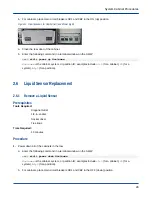
31. Power up all of the cabinets in the row.

a. For blower cabinets, place the MAIN DISCONNECT switch on the rear panel of the blower cabinet PDU

in the ON (up) position.

b. For cabinets, place main circuit breakers CB1 and CB2 in the ON (up) position.

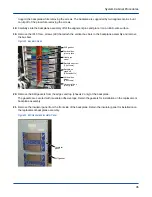
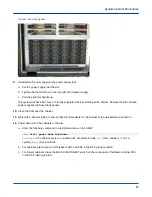
Figure 29. Circuit Breakers for Cabinet (left) and Blower (right)

a. Close the rear door of the cabinet.

b. Enter the following command in a terminal window on the SMW:

smw$ 

xtcli power up Hostname

Hostname

 is the cabinet, system, or partition ID; examples include 

c0-0

 (for a cabinet), 

S0

 (for a

system), or 

p0

 (for a partition).

2.8

Power Distribution Unit (PDU) Replacement

2.8.1

Remove a Power Distribution Unit (PDU)

Prerequisites

Tools Required:

T15 Torx driver

T25 Torx driver

Large slotted screwdriver

Time Required:

15 minutes

About this task

This procedure may require a Cray contracted or customer contracted electrician to complete lockout/tagout
procedures or disconnect facility power. Allow time in the preventive maintenance schedule for this requirement.

This procedure should be preformed only by qualified Cray personnel.

DANGER:

Electrocution Hazard

System Cabinet Procedures


 41

Summary of Contents for XC30-LC

Page 1: ...XC30 LC and XC40 LC Repair Procedures 2 0 H 8002 Rev A...

Page 2: ...Sensor Replacement 29 2 6 1 Remove a Liquid Sensor 29 2 6 2 Install a Liquid Sensor 30 2 7 Chassis Backplane Replacement 31 2 7 1 Remove a Chassis Backplane 31 2 7 2 Install a Chassis Backplane 36 2...

Page 3: ...rned Water Valve Actuator 77 2 19 Spring Returned Water Valve Actuator Replacement 80 2 19 1 Remove a Spring Returned Water Valve Actuator 80 2 19 2 Install a Spring Returned Water Valve Actuator 82 2...

Page 4: ...signed Preconditioner Water Pressure Transducer Replacement 115 4 5 1 Remove a Redesigned Preconditioner Water Pressure Transducer 115 4 5 2 Install a Redesigned Preconditioner Water Pressure Transduc...

Page 5: ...ement 156 5 10 1 Remove a QPDC 157 5 10 2 Install a QPDC 158 5 11 XPDC Replacement 159 5 11 1 Remove a XPDC 159 5 11 2 Install an XPDC 160 5 12 SGDC Replacement 161 5 12 1 Remove a SGDC 161 5 12 2 Ins...

Page 6: ...rary functions command line prompts screen output file path names key strokes e g Enter and Alt Ctrl F and other software constructs Monospaced Bold Indicates commands that must be entered on a comman...

Page 7: ...sublicense from LMI the exclusive licensee of Linus Torvalds owner of the mark on a worldwide basis Other trademarks used in this document are the property of their respective owners 1 1 Safety Infor...

Page 8: ...SD wrist strap ESD and Safety Guidelines H 0016 contains information about safety procedures and potential hazards Read these guidelines before servicing any Cray systems CAUTION Equipment damage Obse...

Page 9: ...ese precautions are not followed WARNING Severe personal injury Ensure that the electrical circuit breakers for the equipment being serviced are off locked and tagged Failure to do so could result in...

Page 10: ...Install a Power Supply 100648000 INTERFACE MODULE OPERATOR Install an Operator Interface on page 25 100692802 ENVIRONMENTAL CONTROL ASSY Install an Environmental Distribution Board on page 27 1006739...

Page 11: ...2 5GBS OPTICAL CXP 30 0M AOC Install an Optical Network Cable AOC on page 65 100424815 CABLE ASSY 12 5GBS OPTICAL CXP 35 0M AOC Install an Optical Network Cable AOC on page 65 100424800 ABLE ASSY 12 5...

Page 12: ...PED PRIOR TO 01 2014 Install a Coil Control Board on page 73 100692701 COIL CONTROL ASSY SYSTEMS SHIPPED AFTER 12 2013 Install a Coil Control Board on page 73 Table 4 XC Series LC System Cabinet Redes...

Page 13: ...tioner Water Pressure and Temperature Transducer on page 114 100513700 SENSOR HUMIDITY TEMP Install a Preconditioner Temperature and Humidity Sensor on page 124 100692700 COIL CONTROL ASSY ON SYSTEMS...

Page 14: ...4 100697700 Module Assy I O Left Install a Blade Using xtwarmswap on page 131 Install a Compute or IO Blade on page 134 100872201 DIFFUSSER MODULE ASSY RIGHT ANC QPDC Install a Blade Using xtwarmswap...

Page 15: ...01 DIMM 16GB DDR4 2133 REG DUAL RANK ECC Install a Blade Memory DIMM on page 136 100961802 DIMM 16GB DDR4 2133 REG DUAL RANK ECC Install a Blade Memory DIMM on page 136 100982901 DIMM 16GB DDR4 2400 R...

Page 16: ...20M CACHE Install a Processor on page 142 100960200 IC INTEL 10 CORE E5 2670 2 5GHZ 25M CACHE 115W C1 Install a Processor on page 142 100960500 IC INTEL 10 CORE E5 2680 2 8GHZ 25M CACHE 115W C1 Instal...

Page 17: ...rocessor on page 142 101534400 IC INTEL 64 CORE 215W 1 3GHZ TDP 7210 Install a Processor on page 142 101534200 IC INTEL 64 CORE 215W 1 3GHZ TDP 7230 Install a Processor on page 142 100845900 DAUGHTER...

Page 18: ...CAL Install a PCI Card on page 169 100900200 PCIE GEN2 10GBE DUAL PORT CX4 INTERFACE Install a PCI Card on page 169 System Maintenance Workstation SMW Replacement procedures for the Dell PowerEdge R81...

Page 19: ...Disk Drive FRU SAS 2 0 1TB 7K2FDE 3 1 2 For 12 Bay Tray Replaced by 100846001 100786901 Disk Drive FRU SAS 2 0 2TB 7K2 FDE 3 1 2 For 12 Bay Tray Replaced by 100846201 100787101 Disk Drive FRU SAS 2 0...

Page 20: ...ples include c0 0 for a cabinet s0 for a system or p0 for a partition The Cabinet ID can be found on the operator interface 2 Open the rear door of the cabinet 3 For compute cabinets place main circui...

Page 21: ...compute cabinets place main circuit breakers CB1 and CB2 in the ON up position Figure 2 Cabinet left and Blower right Circuit Breaker 3 Close the rear door of the cabinet 4 Enter the following comman...

Page 22: ...ocedure 1 Open the rear door of the cabinet 2 Loosen the thumb screw completely and pull the extractor lever forward 3 CAUTION Equipment damage Use both hands to support the power supply and do not ca...

Page 23: ...s operating Procedure 1 Inspect the connectors on the back of the replacement power supply ensure that the pins are straight 2 Slide the power supply into the rack and seat it firmly 3 Push the extrac...

Page 24: ...cuit breakers CB1 and CB2 in the OFF down position c For blower cabinets place the MAIN DISCONNECT switch on the rear panel of the blower cabinet PDU in the OFF down position Figure 5 Circuit Breakers...

Page 25: ...nformation does not need to be reset when replacing the operator interface Procedure 1 Position the operator interface in the cabinet and reinstall the 5 16 in nuts 4 Figure 7 Operator Interface Opera...

Page 26: ...onmental Distribution Board Replacement 2 5 1 Remove an Environmental Distribution Board Prerequisites Tools Required Small Phillips screwdriver Slotted screwdriver 5 16 in socket Socket driver Time R...

Page 27: ...ribution board and label all cables 4 Label all serial cables 5 Loosen the screws 2 that secure each serial cable to the environmental distribution board 6 Disconnect the cables 7 Remove the 5 16 in n...

Page 28: ...Board Connections J1 J2 P8 P1 P2 P3 P4 P5 P6 P9 To cabinet controller Preconditioner Optional Blower control to blower enclosure Power supply rack shelf 0 bottom Power supply rack shelf 1 middle Powe...

Page 29: ...r p0 for a partition 2 6 Liquid Sensor Replacement 2 6 1 Remove a Liquid Sensor Prerequisites Tools Required Diagonal cutter 1 4 in socket Socket driver Tie straps Time Required 15 minutes Procedure 1...

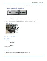
Page 30: ...traps that secure the liquid sensor cable to the adjacent control cables 5 Remove the 1 4 in nuts 2 that attach the liquid sensor to the cabinet and remove the sensor Figure 15 Liquid Sensor Liquid se...

Page 31: ...s CB1 and CB2 in the ON up position Figure 17 Circuit Breakers for Cabinet left and Blower right a Close the rear door of the cabinet b Enter the following command in a terminal window on the SMW smw...

Page 32: ...to complete lockout tagout procedures or disconnect facility power Allow time in the preventive maintenance schedule for this requirement Procedure 1 Power down all of the cabinets in the row a Enter...

Page 33: ...backplane connectors 6 Slide the chassis host approximately 2 inches out from the front of the chassis to disconnect the chassis host from the backplane connectors 7 Open the rear door of the cabinet...

Page 34: ...move the cap Chassis 0 and 2 have one cap chassis 1 has two caps Figure 20 Upper Bus Cover Cap C0S15 C0S14 C0S13 C0S12 C0S11 C0S10 C0S9 C0S8 J1 J2 J3 J4 J5 J16 J17 J18 J19 J20 J11 J12 J13 J14 J25 J6 J...

Page 35: ...efully pull the heat pipes out of the tabs that secure them to the optical network cable connectors 14 CAUTION Equipment loss Insert foam or other material between the vertical bus bar cover and bus b...

Page 36: ...Vertical bus joiner plate Heat pipe screw Backplane screw 16 screws Backplane standoff 28 standoffs Vertical bus screw 48 screws Horizontal bus joiner plate 20 Remove the EMI gaskets from the edges a...

Page 37: ...e an initial torque and a torque verify performed by a second person during reassembly About this task This procedure may require a Cray contracted or customer contracted electrician to complete locko...

Page 38: ...washers is such that the washers compress when the bolts are tightened 11 Position the joiner plates on the vertical buses and reinstall but do not tighten the 7 16 in nuts 20 Chassis 0 and 2 have one...

Page 39: ...h slot and then tighten the associated electrical network alignment block screws 4 Figure 26 Alignment Blade Tool 18 Inspect the heat pipes to ensure that the thermal pad is properly positioned and th...

Page 40: ...ane and reinstall the IP15 Torx screws Ensure that the EMI gasket is centered around each optical network cable connector Figure 28 Optical Network Cable Connector EMI gasket Optical connector Bus cov...

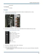
Page 41: ...ystem or partition ID examples include c0 0 for a cabinet S0 for a system or p0 for a partition 2 8 Power Distribution Unit PDU Replacement 2 8 1 Remove a Power Distribution Unit PDU Prerequisites Too...

Page 42: ...d CB2 in the OFF down position c For blower cabinets place the MAIN DISCONNECT switch on the rear panel of the blower cabinet PDU in the OFF down position Figure 30 Circuit Breakers for Cabinet left a...

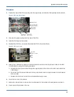
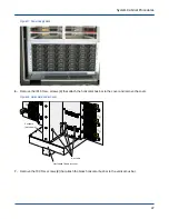
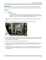
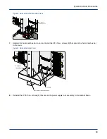
Page 43: ...Figure 32 PDU Power Cable Clamps Ground block Circuit breaker input terminals IP25 TORX screws 6 PDU power cable clamp PDU power cable clamp 2 8 2 Install a Power Distribution Unit PDU Prerequisites...

Page 44: ...CB1 5 Have a Cray contracted or customer contracted electrician reconnect the input power cables to the PDU circuit breakers by using the following procedure a Reinstall the input power cables throug...

Page 45: ...clude c0 0 for a cabinet S0 for a system or p0 for a partition 2 9 Power Supply Rack Replacement 2 9 1 Remove a Power Supply Rack Prerequisites Tools Required T25 Torx driver T30 Torx driver IP25 Torx...

Page 46: ...e site electrician to verify that circuit breakers for the cabinet at the wall panel are off Use appropriate lockout tagout or other site specific procedures to indicate that the breakers are off 3 Op...

Page 47: ...and remove the cover Figure 38 Horizontal Bus Bar Cover C0S9 C0S8 C0S4 C0S3 C0S2 C0S1 C0S0 J25 J23 J6 J7 J8 J9 J10 J1 J2 J3 J4 J5 4 screws 4 screws not shown Horizontal bus bar cover 7 Remove the T30...

Page 48: ...eavy equipment The power supply rack and the horizontal bus bar assembly weigh 118 lbs 54 kg The power supply rack must be removed with the assistance of a qualified personnel Failure to do so may res...

Page 49: ...and power cables 6 to the back of the power supply rack 3 Position the back of the power supply rack assembly onto the support rails and slide the power supply rack into the cabinet Pull cables back t...

Page 50: ...the IP15 Torx screws 8 that secure the horizontal bus bar to the cover Figure 41 Horizontal Bus Bar Cover C0S9 C0S8 C0S4 C0S3 C0S2 C0S1 C0S0 J25 J23 J6 J7 J8 J9 J10 J1 J2 J3 J4 J5 4 screws 4 screws no...

Page 51: ...Work with a site electrician to ensure that circuit breakers for the cabinet at the wall panel are turned on 12 Power down all of the cabinets in the row a Enter the following command in a terminal wi...

Page 52: ...r down all of the cabinets in the row a Enter the following command in a terminal window on the SMW smw xtcli power down Hostname Hostname is the cabinet system or partition ID examples include c0 0 f...

Page 53: ...Install a Cabinet Controller Prerequisites Tools Required Small slotted screwdriver Time Required 5 minutes About this task Procedure 1 Align the guide rail on the cabinet controller with the guide s...

Page 54: ...tname Hostname is the cabinet system or partition ID examples include c0 0 for a cabinet S0 for a system or p0 for a partition 2 11 Cabinet Controller Backplane Replacement 2 11 1 Remove a Cabinet Con...

Page 55: ...in the OFF down position c For blower cabinets place the MAIN DISCONNECT switch on the rear panel of the blower cabinet PDU in the OFF down position Figure 48 Circuit Breakers for Cabinet left and Blo...

Page 56: ...from slot 15 7 Push the backplane assembly towards the front of the cabinet 8 Working from the front of the cabinet slide the backplane assembly out and set it on an ESD safe surface 2 11 2 Install a...

Page 57: ...e rail on the cabinet controller backplane with the guide slot in the front of the chassis 2 Slide the backplane assembly into the chassis until it stops 3 Make sure slot 15 is empty 4 Working from th...

Page 58: ...owing command in a terminal window on the SMW smw xtcli power up Hostname Hostname is the cabinet system or partition ID examples include c0 0 for a cabinet S0 for a system or p0 for a partition 2 12...

Page 59: ...t 2 Open the front door of the cabinet 3 Disconnect the SMW ethernet cables and side band cables 4 Remove the cabinet controller 5 Remove the T15 Torx screws 11 that attach the shroud to the cabinet c...

Page 60: ...end seated before the other end the DIMM or the blade can be damaged Position the DIMM into the socket and simultaneously push down on both ends of the card with thumbs until the card seats and the ca...

Page 61: ...sites Tools Required Small slotted screwdriver Time Required 5 minutes About this task An XC Series AC Chassis Host Replacement video is available which shows how to remove and install this component...

Page 62: ...s host 4 Simultaneously push the release button on the end of both extractor handles and pull out on the handles until they stop 5 Slide the chassis host straight out of the cabinet and set it on an E...

Page 63: ...and serial cables to the front of the chassis host 6 Close the door to the front cabinet 7 Power up all of the cabinets in the row a For blower cabinets place the MAIN DISCONNECT switch on the rear p...

Page 64: ...semblies as a result of mishandling during the installation extraction or return shipping may void the manufacture warranty ESD smocks and shoes must be worn when handling the AOC cables to prevent po...

Page 65: ...2 14 2 Install an Optical Network Cable AOC Prerequisites Tools Required Cable wrap Diagonal cutter Time Required 15 minutes About this task The cabinets and blade slots on the XC30 LC and XC40 LC sy...

Page 66: ...have a tendency to curve or twist in a particular direction Allow the cable to follow its natural path whenever possible 3 Align the end of the cable with the backplane connector and push squarely an...

Page 67: ...h up the release tab at the top of the cable connector and pull the cable straight out of the connector 4 Repeat 2 on page 67 and 3 on page 67 for the other end of the cable 5 Remove the cable from th...

Page 68: ...s or pins and that the chamfered surfaces on the cable connector are not scratched or dented 3 Align the end of the cable with the backplane connector and push squarely and firmly on the cable to seat...

Page 69: ...on b For cabinets place main circuit breakers CB1 and CB2 in the OFF down position c For blower cabinets place the MAIN DISCONNECT switch on the rear panel of the blower cabinet PDU in the OFF down po...

Page 70: ...task The temperature and humidity sensor can only be replaced on the most upstream with no preconditioner or downstream end cabinet Procedure 1 Connect the new sensor to the control cable connector a...

Page 71: ...up position b For cabinets place main circuit breakers CB1 and CB2 in the ON up position Figure 66 Circuit Breakers for Cabinet left and Blower right a Close the rear door of the cabinet b Enter the f...

Page 72: ...er for the cabinet is off locked and tagged Failure to do so could result in severe shock and burns Work with a site electrician to ensure that circuit breakers for the cabinet at the wall panel are o...

Page 73: ...required to access the coil control board and label all cables 6 Loosen the small captive Phillips screws 2 that secure the serial cable to the coil control board and disconnect the cable Serial cable...

Page 74: ...screws 3 Reconnect the control cables to the coil control board P6 Environmental distribution board P1 Temperature sensors P3 Moisture sensor P5 Actuator P2 Transducer 4 Reconnect the high speed netw...

Page 75: ...ng Returned Water Valve Actuator Replacement 2 18 1 Remove a Non Spring Returned Water Valve Actuator Prerequisites Tools Required Diagonal cutter Tie straps Phillips screwdriver Hex head tool Time Re...

Page 76: ...lower cabinets place the MAIN DISCONNECT switch on the rear panel of the blower cabinet PDU in the OFF down position Figure 71 Circuit Breakers for Cabinet left and Blower right 2 Open the rear door o...

Page 77: ...Phillips screwdriver Hex head tool Time Required 8 10 minutes About this task CAUTION Equipment damage It s recommended to perform this procedure on a powered down cabinet If performed on a powered u...

Page 78: ...he water valve actuator handle to disconnect the handle from the actuator c Place the actuator shaft in the opening The shaft only fits in the correct orientation d Pull the connecting screw slightly...

Page 79: ...ts place main circuit breakers CB1 and CB2 in the ON up position Figure 74 Circuit Breakers for Cabinet left and Blower right a Close the rear door of the cabinet b Enter the following command in a te...

Page 80: ...the current power consumption and utilization of the system Be cautious of workload increases or decreases Significant workflow changes that occur after the system is in manual mode could lead to cab...

Page 81: ...ute Cab Water Valve Position 39 00 pct c2 0 Message Compute Cab Water Valve Position 38 00 pct c1 1 Message Compute Cab Water Valve Position 40 00 pct c0 1 Message Compute Cab Water Valve Position 38...

Page 82: ...from the coil control board 2 19 2 Install a Spring Returned Water Valve Actuator Prerequisites Tools Required Diagonal cutter Tie straps Phillips screwdriver Hex head tool Time Required 8 10 minutes...

Page 83: ...ndle on the actuator and push firmly to seat the handle 4 Replace the tie straps that secure the control cables 5 Power up all of the cabinets in the row a For blower cabinets place the MAIN DISCONNEC...

Page 84: ...or a system or p0 for a partition b For cabinets place main circuit breakers CB1 and CB2 in the OFF down position c For blower cabinets place the MAIN DISCONNECT switch on the rear panel of the blower...

Page 85: ...wrench 4 Open the chilled water transducer valve to inspect for leaks If leaks are found tighten the tranducer with the wrench until the leak steps 5 Reconnect the control cable to the transducer 6 Sl...

Page 86: ...row a Enter the following command in a terminal window on the SMW smw xtcli power down Hostname Hostname is the cabinet system or partition ID examples include c0 0 for a cabinet S0 for a system or p...

Page 87: ...from the chilled water transducer valve 11 Use absorbent rags to clean up any water 2 21 2 Install an Original Water Pressure and Temperature Transducer Prerequisites Tools Required 7 8 in wrench Abs...

Page 88: ...f the blower cabinet PDU in the OFF down position Figure 80 Circuit Breakers for Cabinet left and Blower right 2 22 Return or Supply Temperature Sensor Replacement 2 22 1 Remove a Return or Supply Tem...

Page 89: ...the new temperature sensor is labeled appropriately 4 CAUTION Personal injury Use caution when cutting the foam with the utility knife Failure to use caution can cause personal injury Cut the foam in...

Page 90: ...iece of adhesive foam over the new temperature sensor 4 Continue adding foam 2 3 pieces until the foam over the temperature sensor is flush with the remaining foam 5 Label the temperature sensor conne...

Page 91: ...the rear door of the cabinet b Enter the following command in a terminal window on the SMW smw xtcli power up Hostname Hostname is the cabinet system or partition ID examples include c0 0 for a cabine...

Page 92: ...en the front or rear door according to the position of the blower 2 Locate the blower assembly that needs to replaced and place the corresponding circuit breaker in the OFF position 3 Remove the 25IP...

Page 93: ...minutes Procedure 1 CAUTION Equipment damage If the system is powered up the blower must be reinstalled within 2 minutes after removing the defective blower Failure to do so can cause the system to o...

Page 94: ...Blower Control Assembly Prerequisites Tools Required T10 Torx driver Time Required Approximately 15 minutes time varies based on the number of compute cabinets in a row Procedure 1 Power down all of t...

Page 95: ...ith missing labels 5 Remove the 10IP Torx screws 10 that attach the blower control cover to the PDU Note the orientation of the blower control assembly to ensure correct installation Figure 86 Blower...

Page 96: ...les 6 3 Reconnect the serial cable and the six control cables to the blower control assembly 4 Reinstall the bottom blowers into the front and rear of the cabinet 5 Close the front door of the cabinet...

Page 97: ...es based on the number of compute cabinets in a row Procedure 1 Power down all of the cabinets in the row a Enter the following command in a terminal window on the SMW smw xtcli power down Hostname Ho...

Page 98: ...2 Blower Cabinet PDU Rear View Cover panel screws 4 Support bracket screws 4 6 Remove 25IP Torx screws 4 that attach the cover panels above the front of the PDU and remove the panels Figure 93 Blower...

Page 99: ...e the control cables 6 and the power cables 6 from the top of the PDU 9 Remove the 25IP Torx screws 4 that attach the PDU to the front frame rails 10 Remove the 15IP Torx screws 4 that attach the supp...

Page 100: ...he adjacent cabinet 2 Reinstall the 25IP Torx screws 4 that attach the PDU to the front frame rails Figure 95 Blower Cabinet PDU Front View Cover panel screws 4 Frame rail screws 4 3 Reinstall the 15I...

Page 101: ...of the PDU is in the OFF position e Reconnect the power cable connector under the raised floor 6 Position the cover panels above the front and rear of the PDU and reinstall the 25IP Torx attachment sc...

Page 102: ...g command in a terminal window on the SMW smw xtcli power up Hostname Hostname is the cabinet system or partition ID examples include c0 0 for a cabinet S0 for a system or p0 for a partition Blower Ca...

Page 103: ...down all of the cabinets in the row a Enter the following command in a terminal window on the SMW smw xtcli power down Hostname Hostname is the cabinet system or partition ID examples include c0 0 for...

Page 104: ...the side panel in a safe location 3 Disconnect the liquid sensor control cable from the coil control board 4 Cut the tie straps that secure the liquid sensor cable to the adjacent control cables 5 Re...

Page 105: ...our remaining quarter turn fasteners with a 5 32 in balldriver wrench to close the side panel 5 Power up all of the cabinets in the row a For blower cabinets place the MAIN DISCONNECT switch on the re...

Page 106: ...binet the procedure must be completed within 15 20 minutes to prevent possible system EPO and or condensation Procedure 1 Power down all of the cabinets in the row a Enter the following command in a t...

Page 107: ...actuator cable to the adjacent control cables if necessary 5 Verify the water valve is in the fully closed position 6 Place a long piece of tape over the actuator indicator dial to hold it in place 7...

Page 108: ...stall the Phillips screw d Remove the tape covering the actuator indicator dial 3 If removed position the handle on the actuator and push firmly to seat the handle 4 Replace the tie straps that secure...

Page 109: ...on a powered up cabinet the procedure must be completed within 15 20 minutes to prevent possible system EPO and or condensation CAUTION Equipment damage This procedure is affected by the current power...

Page 110: ...Valve Position c3 1 Message Precond Cab Water Valve Position 42 00 pct c4 0 Message Precond Cab Water Valve Position 40 00 pct c6 0 Message Precond Cab Water Valve Position 38 00 pct c6 1 Message Prec...

Page 111: ...ng piece of tape over the actuator indicator dial to hold it in place 7 Remove the Phillips screw that attaches the actuator to the valve and remove the actuator 8 Disconnect the water valve actuator...

Page 112: ...mly to seat the handle 4 Replace the tie straps that secure the control cables 5 From the SMW reactivate HSS dynamic control smw echo 1 temp_close_loop 6 Replace the EMI filter side panel a Lift the s...

Page 113: ...the cabinets in the row a Enter the following command in a terminal window on the SMW smw xtcli power down Hostname Hostname is the cabinet system or partition ID examples include c0 0 for a cabinet...

Page 114: ...the chilled water transducer valve Figure 108 Water Pressure and Temperature Transducer 7 Use absorbent rags to clean up any water 4 4 2 Install an Original Preconditioner Water Pressure and Temperat...

Page 115: ...and in a terminal window on the SMW smw xtcli power down Hostname Hostname is the cabinet system or partition ID examples include c0 0 for a cabinet S0 for a system or p0 for a partition b For cabinet...

Page 116: ...nets place the MAIN DISCONNECT switch on the rear panel of the blower cabinet PDU in the OFF down position Figure 111 Circuit Breakers for Cabinet left and Blower right 2 Open the rear door of the cab...

Page 117: ...til the leak steps 5 Reconnect the control cable to the transducer 6 Slide the protective foam cover over the valve and secure the cover with Velcro 7 Power up all of the cabinets in the row a For blo...

Page 118: ...ow a Enter the following command in a terminal window on the SMW smw xtcli power down Hostname Hostname is the cabinet system or partition ID examples include c0 0 for a cabinet S0 for a system or p0...

Page 119: ...knife and remove it Use the new temperature sensor to estimate how much foam to remove The opening should be approximately 0 5 to 1 5cm larger than the sensor 5 Peel off the old temperature sensor fr...

Page 120: ...erature sensor connectors into the coil control board 7 Connect the new temperature sensor to the same location as the old temperature sensor Location P10 is the supply sensor and location P11 is the...

Page 121: ...name is the cabinet system or partition ID examples include c0 0 for a cabinet S0 for a system or p0 for a partition b For cabinets place main circuit breakers CB1 and CB2 in the OFF down position c F...

Page 122: ...the row a For blower cabinets place the MAIN DISCONNECT switch on the rear panel of the blower cabinet PDU in the ON up position b For cabinets place main circuit breakers CB1 and CB2 in the ON up po...

Page 123: ...akers CB1 and CB2 in the OFF down position c For blower cabinets place the MAIN DISCONNECT switch on the rear panel of the blower cabinet PDU in the OFF down position Figure 117 Circuit Breakers for C...

Page 124: ...nnector 4 8 2 Install a Preconditioner Temperature and Humidity Sensor Prerequisites Tools Required T10 Torx driver Phillips screwdriver Balldriver Set 11 Piece 5 64 3 8 in Time Required Approximately...

Page 125: ...asteners with a 5 16 in balldriver wrench d Turn the four remaining quarter turn fasteners with a 5 32 in balldriver wrench to close the side panel 5 Power up all of the cabinets in the row a For blow...

Page 126: ...same for the original and new coil control boards DANGER Electrical hazard Make sure that the electrical circuit breaker for the cabinet is off locked and tagged Failure to do so could result in sever...

Page 127: ...ntrol board 4 9 2 Install a Preconditioner Coil Control Board Prerequisites Tools Required Small Phillips screwdriver Slotted screwdriver T15 Torx screwdriver Socket driver Time Required 15 minutes Ab...

Page 128: ...cabinets in the row a For blower cabinets place the MAIN DISCONNECT switch on the rear panel of the blower cabinet PDU in the ON up position b For cabinets place main circuit breakers CB1 and CB2 in...

Page 129: ...occur if an I O blade is warm swapped during system operation CAUTION Equipment damage A slot cannot be left empty for more than two minutes on a running system Leaving a slot empty for more than two...

Page 130: ...the SMS as crayadm halt jobs on the admindown slots smw xtcli halt BladeID 3 Route the high speed network around the blade to be removed and wait for this command to complete smw xtwarmswap r BladeID...

Page 131: ...ls Required T15 Torx driver Time Required 5 minutes Procedure 1 If installing an unpopulated spare blade acclimatize the blade to the computer room before removing it from the shipping case reinstall...

Page 132: ...to xtalive before continuing smw xtalive BladeID 11 Check the status of the blade slot smw xtcli status t BladeID 12 Power down then power up components in the Cray system smw xtbounce BladeID 13 Upda...

Page 133: ...pute or IO Blade Prerequisites Tools Required T15 Torx driver Time Required 5 minutes About this task Use this procedure when the operating system is not running If the operating system is running use...

Page 134: ...tom of the blade near the center with the other hand and pull the blade completely out of the cabinet 8 Set the blade on an ESD safe surface 9 If returning a blade to Logistics remove all of the daugh...

Page 135: ...gers under the extractor handles 6 Engage the tabs on the extractor handles with the extractor flanges on the sides of the cage 7 Simultaneously push in on both extractor handles until they lock in pl...

Page 136: ...s the release tab and pull cable straight out and remove the power cable assembly 5 Locate the defective DIMM 6 Simultaneously push out on both DIMM cams with both thumbs to eject the DIMM from the so...

Page 137: ...e b Insert the two tabs on the center of the cable into the standoffs on the blade c Reconnect the cable connectors 4 Replace the air diffuser bracket and reinstall the T10 Torx screws Torque screws t...

Page 138: ...IVOC remove the two IP15 Torx screws that attach the voltage module to the daughter card 7 Remove the voltage module If removing an Aries VRM or CPU VRM grab the corners of the voltage module and care...

Page 139: ...he connector Inserting the wrong replacement component into a connector can result in equipment damage Spray the voltage module contacts and the voltage module socket with dusting gas to remove any de...

Page 140: ...r cable connectors press the release tab and pull cable straight out and remove the power cable assembly 5 Locate the defective processor and remove the processor air duct covering it 6 Loosen the cap...

Page 141: ...ment Damage Be careful not to drop the processor on the socket pins If the processor is dropped into the socket the pins in the socket can be damaged Press the vacuum release button and attach the pen...

Page 142: ...e surface Figure 128 Processor Install Tool Attach Protect socket pins Released 5 7 2 Install a Processor Prerequisites Tools Required Adjustable torque driver 5 40 in lb T10 Torx bit T15 Torx bit Dus...

Page 143: ...ssor 90 degrees If the processor is forced into the socket the processor or blade may be damaged CAUTION Equipment Damage Be careful not to drop the processor on the socket pins If the processor is dr...

Page 144: ...the vacuum release button on the pickup pen to release the processor Figure 131 Processor Install Tool Release Press 4 Close the socket cover 5 Close the lever near the locked symbol and the second le...

Page 145: ...the heat sink on the processor socket If more than one processor heat sink was removed each heat sink needs to be reinstalled in its original position Processor heat sinks are not interchangeable 9 C...

Page 146: ...r cable assembly on the blade b Insert the two tabs on the center of the cable into the standoffs on the blade c Reconnect the cable connectors 13 Replace the air diffuser bracket and reinstall the T1...

Page 147: ...ve the bracket 4 Disconnect the power cable connectors press the release tab and pull cable straight out and remove the power cable assembly 5 Locate the defective processor and remove the processor a...

Page 148: ...from the thermal grease 8 Locate a flat slot between the processor tray and the heatsink Figure 137 Processor Tray Slot 9 Insert a flathead screwdriver into the slot and gently pry the processor tray...

Page 149: ...re 139 Remove Processor from Tray 11 Still handling the processor from the sides set it in a holding tray and clean off the thermal grease with a plastic scrapper and isopropyl alcohol Figure 140 Clea...

Page 150: ...e face of the processor chip This will damage the chip Procedure 1 Place the processor in the processor tray a Hold the processor from the sides with two fingers and line up the gold triangle on the c...

Page 151: ...le 4 Line of the holes at the top of both the heatsink and processor tray Figure 144 Line Up Processor Tray with Heatsink 5 Snap down the retaining clips to secure the processor tray to the heatsink W...

Page 152: ...are clean and undamaged 7 Place the heatsink by lining up the heatsink the two pins one skinny and one fat to the corresponding holes on the heatsink Figure 146 Replace Heatsink on KPDC 8 Tighten the...

Page 153: ...e processor 10 Install the power cable assembly a Position the power cable assembly on the blade b Insert the two tabs on the center of the cable into the standoffs on the blade c Reconnect the cable...

Page 154: ...ress the release tab and pull cable straight out and remove the power cable assembly 5 Locate the defective KPDC and remove the processor air ducts covering it 6 Remove the standoffs 6 that attach the...

Page 155: ...KPDC will be damaged Ensure the small standoff on each side of the blade is in the position labeled B Figure 148 KPDC Standoff Position 2 Position the replacement KPDC on the blade and press down firm...

Page 156: ...s and position the power cable assembly on the blade 8 Install the power cable assembly a Position the power cable assembly on the blade b Insert the two tabs on the center of the cable into the stand...

Page 157: ...and remove the bracket 4 Disconnect the power cable connectors press the release tab and pull cable straight out and remove the power cable assembly 5 Locate the defective QPDC and remove the process...

Page 158: ...tandoffs to 14 in lbs The bit holder on the torque driver is the same size as the standoff 3 Record the location of the DIMMs and processors on the defective QPDC to reinstall them in the same locatio...

Page 159: ...the air diffuser bracket to the blade and remove the bracket 4 Disconnect the power cable connectors press the release tab and pull cable straight out and remove the power cable assembly 5 Locate the...

Page 160: ...ndoffs 6 that attach the XPDC to the blade Torque the standoffs to 14 in lbs The bit holder on the torque driver is the same size as the standoff 3 Record the location of the DIMMs VRMs and processors...

Page 161: ...DC Procedure 1 Remove the blade from the cabinet 2 Remove the T15 Torx screws that attach the shroud to the blade and remove the shroud 3 Remove the T10 Torx screws that attach the air diffuser bracke...

Page 162: ...t SGDC on the blade and press down firmly in the area of the connector to seat it in the connector on the blade 2 Hand tighten the standoffs 2 that attach the KPDC to the blade Torque the standoffs to...

Page 163: ...rocedure 1 Remove the blade from the cabinet 2 Remove the T15 Torx screws that attach the shroud to the blade and remove the shroud 3 Remove the T10 Torx screws that attach the air diffuser bracket to...

Page 164: ...d processors from the defective GPDC to the new GPDC Procedure 1 Position the replacement GPDC on the blade and press down firmly in the area of the connector to seat it in the connector on the blade...

Page 165: ...ove a HPDC transfer the DIMMs and processors to an unpopulated spare HPDC and install the HPDC About this task If installing a spare HPDC transfer the DIMMs and processors from the defective HPDC to t...

Page 166: ...g upward Place the HPDC down directly and do not drag the HPDC on the surface Failure to do so can lead to component damage Place the HPDC on an ESD safe surface with components facing upward 5 14 2 I...

Page 167: ...ducts and position the power cable assembly on the blade 7 Install the power cable assembly a Position the power cable assembly on the blade b Insert the two tabs on the center of the cable into the s...

Page 168: ...I riser c Remove the PCI riser near the lower mezzanine d Repeat to remove the opposite PCI mezzanine and PCI riser if necessary 4 Remove the top T10 Torx screw that attaches the aluminum block to the...

Page 169: ...card first 2 Repeat for the second PCI card if necessary 3 Reinstall the top T10 Torx screw that attaches the aluminum block to the PCI faceplate 4 Spray the PCI riser socket and mezzanine contacts wi...

Page 170: ...eplacement IOBB IO blade The defective IOBB is not removed from the IO blade The defective IOBB and IO blade are returned to logistics Procedure 1 Remove the blade from the cabinet 2 Remove the T15 To...

Page 171: ...O blade are returned to logistics Procedure 1 Install the PDC that connect to the IOBB 2 Place the processor air duct over the PDCs 3 Install the PCIe cards risers and mezzanines 4 Install the power c...

Page 172: ...lable on the Dell Website at http www dell com support Dell system workstation parts may be under warranty Each XC30 LC and XC40 LC system requires one rack mount SMW The SMW server is available in a...

Page 173: ...et Field replacement procedures FRPs for the NetApp E2600 are available for download at the NetApp support website at http www netapp com To access the documentation register for a NetApp account Boot...

Reviews: