background image

Page 12

Vortex8 User Manual

Version 1.2

4.4 Installing a Dome

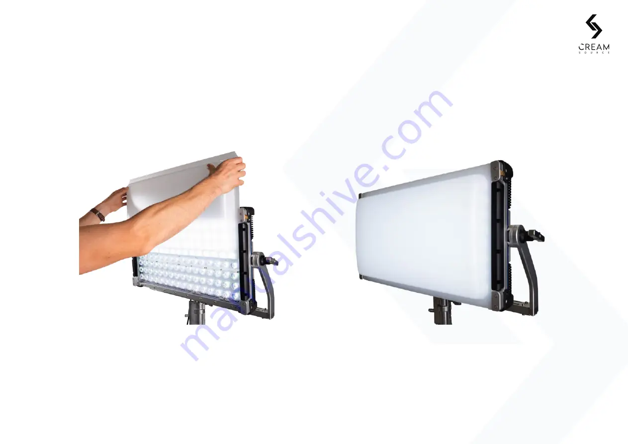
Installing the Dome the Vortex8 widens the native 20° beam angle. This modifier softens the source and
reduces shadowing.

Install the Dome into the safety filter rail as per steps above in the “Rails Filter” section.

4. Transport and Safety

Slide the dome into the first filter rail.

Push top latch down to engage the lock on
each side.

Summary of Contents for Vortex 8

Page 1: ...Support Have any questions Feel free to get in touch https creamsource com support ...

Page 2: ... 21 Notifications Tray Status Bar 5 22 User Presets 5 23 Storing a User Preset 5 24 Restoring a User Preset 5 25 Clearing a User Presets 5 26 Clear All User Presets 5 27 Menu Functions 6 Connectivity 6 1 Best Of Class Connectivity 6 2 Wired DMX Control 6 3 Wireless DMX Control 6 4 Streaming ACN sACN 6 5 Wired Remote Dimmer 6 6 Link Multiple Vortex8 Fixtures 6 7 Firmware Updates Via USB 7 Camera Sy...

Page 3: ...d dust wont hold the Vortex8 back Connectivity to the Vortex8 is well up to date with LumenRadio TimoTwo built in Ethernet Bluetooth 5pin DMX Wifi USB type A and Creamsource Accessory port Interaction between Vortex8 and various third party instruments and protocols are endless opening various wired and wireless control options We are geeks for high quality and precision engineering and loads of o...

Page 4: ...the Vortex8 1 2 Part Numbers The table below lists part numbers for the Creamsource Vortex system Part Number Description K CSV 8 ESS Vortex8 Essentials Kit Includes Fixture Yoke Power Cable Flat Diffuser CSV 8 Vortex8 650W Colour Fixture Head Only ...

Page 5: ...ended for permanent outdoor use Temporary outdoor use only This product is intended for professional use and may only be operated by qualified persons Do not cover the ventilation slots on the side and rear of the Vortex8 Airflow is required for cooling and operation Inspect the power cable for damage prior to operation Always ensure that the fixture is earthed electrically The fixture may become ...

Page 6: ...use harmful interference and 2 This device must accept any interference received including interference that may cause undesired operation Certifications CE FCC RCM Please make sure discarded electrical waste is properly recycled to reduce environmental impact Please use a separate collection facility or contact the supplier from which this fixture was purchased 1 About the Vortex8 IP65 ...

Page 7: ...Page 7 Vortex8 User Manual Version 1 2 Vortex8 Yoke AC PowerCON Cable T30 Torx Key 2 1 What s in the Box Vortex8 ships with the following items included in the box 2 Getting started 1 2 3 4 ...

Page 8: ... fixture and will get quite hot during operation especially on the aluminium chassis due to heat dissipation Care must be taken when handling the Vortex8 The maximum surface temperature of the lamp head will be 60 C 140 F when operated in an ambient temperature of 25 C 77 F Maximum ambient temperature for normal operation is 40 C 104 F 3 Water and Temperature The supplied PowerCon cable must be us...

Page 9: ...system that is assembled using a T30 Torx tool provided The standard yoke allows for mounting to a combo stand with a standard baby pin receiver 4 Transport and Safety Included parts Use the hex key to fix yoke arms to base Repeat on the other side Adjust until finger tight do not over tighten 1 2 4 3 ...

Page 10: ...m to support complex rigging setups and Vortex8 arrays Ensure that mounting point is safe and secure and is rated to take the full unit weight Ensure fastener length does not exceed the depth of the threaded rigging point or they may become stuck 4 Transport and Safety RIGGING POINT RIGGING POINT RIGGING POINT ...

Page 11: ...d a honeycomb grid Accessories slide into the rail system and lock securely with unique lock and latch system 4 Transport and Safety The filter rail slot has a unique locking mechanism that locks the initial filter in while allowing second filter to be inserted without unlocking Push top latch down to engage the lock Push gold button to release to unlock Latch in unlock position 1 3 2 4 ...

Page 12: ...widens the native 20 beam angle This modifier softens the source and reduces shadowing Install the Dome into the safety filter rail as per steps above in the Rails Filter section 4 Transport and Safety Slide the dome into the first filter rail Push top latch down to engage the lock on each side ...

Page 13: ...ycomb The honeycomb reduces the beam angle and stops ambient spill of light This works great in with the standard diffuser in the second slot 4 Transport and Safety Slide the honeycomb into the first filter rail Push top latch down to engage the lock on each side ...

Page 14: ...The standard diffuser softens the native hard light and widens the beam angle This modifier works well inconjunction with the dome and the honecomb 4 Transport and Safety Slide the diffuser into the first filter rail Push top latch down to engage the lock on each side ...

Page 15: ...ote dimmer control sold separately sACN over ethernet connection EXT MENU takes you to the home screen and back a screen while in a function SELECT enters into the active function Navigation DMX quick Ambient Encoder nav Access button light sensor wheel LCD display Quick select Level shortcut Flash Button Power Button with CreamOS buttons dock buttons button trigger effects Turns the LED panel On ...

Page 16: ...m based on architecture that is robust and expandable CreamOS continues to evolve with easy access and a user friendly interface CreamOS is driven by the following screens 5 Controls Colour Mode Effects Mode Home screen Settings screen Visit www creamsource com support for the latest version of CreamOS ...

Page 17: ...the functions from the home screen 5 Controls Quick select parameter dock Notifications tray Current mode Selected parameter tile Colour mode Effects mode User Presets Next Page Hold to access User Preset when Next Page is shown Hold to turn off an Effect When orange Effects Mode is on Level X F ...

Page 18: ...Colour mode description Notifications tray Cycle forward Cycle back Select mode CCT XY CCT RGBW HSV GELS CCT XY RGBW CCT HSV CCT GELS 5 5 CreamOS Colour Mode Easily switch Colour modes from this screen For more information about the Colour Mode menu go to 5 7 Menu Functions ...

Page 19: ...eters that can be changed to customise the effects 5 Controls Selected effect Effect description Notifications tray Current mode Cycle forward Cycle back Select mode Effects Off Dual Level Calibrate Sync Sync Flash Random Flash Frames Television Paparazzi Candle Fire Party Colour Cycle Emergency Pulse Strobe More effects may be added in future firmware updates Visit www creamsource com support for...

Page 20: ...m Candle 3 Windy Candle 4 Fireplace 5 Campfire 6 Bonfire 7 Inferno 8 Gas Fire INTENSITY 0 100 Intensity of effect amount brightness can vary by SPEED 0 100 Speed that the effect will flicker COLOUR 1400 5600k Custom The colour temperature of the effect If set to Custom can use any colour set in Colour Mode screen SETTING RANGE DESCRIPTION PRESET 1 14 Choose from presets that will save time for set...

Page 21: ...TTING RANGE DESCRIPTION SPEED 0 100 Speed of effect DYNAMIC RANGE 0 100 Dynamic range of effect amount brightness can vary by CCT 2200 10000k Base CCT for the effect SETTING RANGE DESCRIPTION PALETTE 1 9 Choose colour palette from the following PRIMARY 6 PRIMARY 12 PRIMARY 24 WARM COOL WARM COOL PASTEL PURPLE RAIN ULTRAVIOLET SPEED 0 100 Speed of the effect TRANSITION 1 3 Change the way the effect...

Page 22: ... camera flash bulb effect with control of speed decay speed and CCT SETTING RANGE DESCRIPTION FREQUENCY 0 100 How often the effect will display PULSE SPEED 0 100 The speed the pulse effect SETTING RANGE DESCRIPTION SPEED 0 100 The speed the colour cycling SETTING RANGE DESCRIPTION SPEED 0 100 Speed of the effect interval between flashes DECAY SPEED 0 100 How quickly the flash fades CCT 1700 15000k...

Page 23: ...ern of flashes with control over frequency length variation SETTING RANGE DESCRIPTION FREQUENCY 0 1 50Hz Frequency of strobe effect DUTY CYCLE 0 100 The ratio between light OFF and ON times SETTING RANGE DESCRIPTION FLASH LEVEL 0 100 Light output when FLASH button pressed on the control panel SETTING RANGE DESCRIPTION FREQUENCY 0 05 5 0Hz Frequency of random effect LENGTH 2 200ms Maximum length of...

Page 24: ...ames e g Flash 1 frame ON followed by 3 frames OFF repeat The Frame Offset is useful if using this effect with multiple fixtures so they can respond to different frames SETTING RANGE DESCRIPTION FLASH LEVEL 0 100 Light output when FLASH triggered FLASH TIME 1 5000th 1 5th sec Duration the light is flashed ON for SETTING RANGE DESCRIPTION OFF LEVEL 0 100 Brightness for the OFF frames FRAMES ON 1 25...

Page 25: ...o prevent the flash banding effects when shooting on a CMOS sensor camera or when using frame synchronised effects such as Flash Frames SETTING RANGE DESCRIPTION SYNC PHASE 0 360 Change the phase offset of the camera sync input Adjust until the flashing light cannot be seen in the camera monitor Ensure that you setup a camera sync signal that is connected to the Accessory port See 7 Camera Sync fo...

Page 26: ...ngs Notifications tray status bar 5 Controls DC Battery Source DC Battery Source Power Limit Set DC Battery Source Power Limit Actived High Speed Fan Speed High Calibrated RGBW LAN Connected Fan Speed Medium Dimming Curve EXP CRMX Linked Signal strength of CRMX Fan Speed Quiet Dimming Curve Log CRMX Disabled Fan Paused Dimming Curve S DMX port used for Sync ...

Page 27: ...ble to store restore and clear User Presets for Effects and Colour modes When creating a User Preset for a Colour mode if an Effect is running the User Preset will store both the Effect and Colour parameters The icon in the User Preset list will display the Effect and not Colour mode icon TIP 5 Controls User Presets shortcut Access the User Preset Options Saved User Preset ...

Page 28: ...o store it to that slot A dialogue message will appear to show it has been stored 1 Go to the User Preset menu 2 Scroll to a slot with the stored User Preset 3 Press Select to restore that User Preset A dialogue will inform you that it has been successfully restored 1 Go to the User Preset menu 2 Scroll to a slot with the stored User Preset 3 Press and hold down Select button A dialogue will show ...

Page 29: ...l over palette speed transition type and transition speed Pulse Pulse of light fading in and out with control of frequency and pulse speed Paparazzi Random camera flash bulb effect with control of speed decay speed and CCT Colour Cycle Cycle through the spectrum of saturated colours with control over speed Strobe Strobe effect with control over frequency brightness duty cycle Random Create a rando...

Page 30: ...3200K High Speed Enables High Speed mode for shooting at high frame rates Disable for best colour accuracy and dimming performance Blackout On Startup Select to force the fixture to power on with the fixture output turned off When DMX is received the fixture will turn on If not selected then fixture will power on with the last used output level Battery Power Limit Set power limit in Watts when run...

Page 31: ...o other Creamsource fixtures Note configuration settings are not transmitted ADVANCED Sync Options Send Sync via DMX Sync signal will be sent over the DMX port Note that normal DMX data is disabled when this is enabled and a status icon will be visible in status bar Receive Sync via DMX The fixture will receive sync signal via DMX port if this is enabled Note that normal DMX data is disabled when ...

Page 32: ... 1 2 6 1 Best Of Class Connectivity Vortex8 is equiped with a wide range of connectivity options both wireless and wired 6 Connectivity DMX In DMX Thru connector etherCON TOP 48V DC power CS Accessory USB A Power Input port Worldwide AC ...

Page 33: ... mapping options 6 3 Wireless DMX Control Every Vortex unit has built in Wireless DMX control using the LumenRadio CRMX system When a valid wireless DMX signal is present the blue Wireless indicator on the keypad will light up The current signal level will also be displayed on the top status area of the OLED screen If wired DMX is connected at the same time as the Wireless DMX is receiving data th...

Page 34: ...ccessory connector on the back of the unit This will allow basic control of the fixture including Brightness Level CCT Tint Hue and Saturation 6 6 Link Multiple Vortex8 Fixtures Enable Master mode under the Link Menu Multiple Creamsource fixtures can be connected together to operate in unison without an external DMX controller Use DMX cable to connect the units Note that configuration and settings...

Page 35: ...ual Version 1 2 6 6 Link Multiple Vortex8 Fixtures Cont Linking to other fixture is a simple process DMX THRU DMX THRU DMX THRU DMX IN DMX IN DMX IN Master Fixture Master Replica Replica Replica Replica Fixture 6 Connectivity ...

Page 36: ...USB connector on Vortex 3 Power up Vortex8 and it will automatically update to the version copied on the USB drive Note Installing will take 1 2 minutes 4 After installation is complete a message will appear to verify it was successful 5 Safely remove USB drive once the update is complete Recommended USB drives include EMTEC Kingston and Toshiba Drives will need to be formatted as FAT32 If the Vor...

Page 37: ... flashing or strobing light source It can also be used for frame accurate strobing for advanced special effects for frame rates up to 5 000fps 7 Camera Sync 1 flashbandit CS Accessory Converter CSU ACC CONV Accessory Input Port 2 3 4 5 6 CS Flashbandit CS SYNC Cinema Camera Sync Input CS Vortex8 Fixture CSV 8 Sync Generator Eg Ambient Lockit BNC T Adpater CS Accessory to BNC Cable CSV ACC BNC Sync...

Page 38: ...ing coaxial cable a blue light on Flashbandit should flash indicating valid signal Once sync is established a green bar will be highlighted on the top of the status bar of the Vortex8 indicating the device is synchronised The frame rate will also be displayed beneath the status bar Calibrate using the Flashbandit see 7 5 Calibrate Sync for details Connect the camera GENLOCK input to the Lockit box...

Page 39: ...ly into the BNC SYNC AUX port of the camera Plug the other end of the Creamsource Accessory to BNC Cable to the Accessory Input port of the Vortex8 Setup the camera to output the sync signal refer to the user manual for device Once sync is established a green bar will be highlighted on the top of the status bar of the Vortex8 indicating the device is synchronised The frame rate will also be displa...

Page 40: ...le Receive Sync via DMX option on the Secondary units under Advanced Sync Option menu You only need to calibrate sync on the Master unit the Secondary units do not need to be calibrated If using Invert Input Level option this only needs to be done on the Master unit 1 2 3 4 5 This status icon is shown if the DMX ports are being used for Camera Sync and cannot be used for transmitting or receiving ...

Page 41: ...g effects when shooting on a CMOS sensor camera If using multiple fixtures with sync distributed by DMX cable only the first unit needs to be calibrated If camera frame rate and or shutter angle is changed it is recommended to re calibrate TIP Point your camera directly at the Vortex8 so the entire frame is covered by the LEDs 1 2 Select Effects Calibrate Sync The fixture will start to flash at th...

Page 42: ...ffects when shooting on a CMOS sensor camera Adjust phase value on Calibrate Sync screen As you change the phase a dark band should appear to move up and down on the camera monitor Adjust until the dark band fills the monitor completely Shooting with wide shutter angles and at higher speeds reduces the size of the dark band making calibration more difficult 3 4 The Vortex8 is now calibrated It can...

Page 43: ...ge is the same as releasing the FLASH button The input level can be inverted by selected Invert Input Level from the Advanced Sync Options menu NOTE An input voltage from 5V 24V can be used for trigger signal The input impedance is 150kΩ 7 6 Shooting While Calibrated Once the Creamsource has been calibrated any of the modes may be used without the possibility of causing torn frames The remote dimm...

Page 44: ...Please contact your nearest authorised repair centre for it to be replaced Require help finding your nearest authorised repair centre Feel free to get in touch https creamsource com support Internal fuse is only for 48V DC not AC input Acceptable Fuses Bel Fuse Inc 0ADKC9200 BE Littelfuse Inc 0215020 MXP 8 Maintenance ...

Page 45: ...ent capacity to continuously power the fixture with a current draw of 13 5A The Vortex requires an input voltage in the range of 45 50V DC Most batteries will have a much larger range than this so a regulated battery system is required to keep within the operating limits of the Vortex The DC input has over voltage and under voltage protection and reverse polarity protection Some power will still b...

Page 46: ... will apply even if AC source is also plugged in Set the limit under MENU Fixture Settings Battery Power Limit The table below shows power requirements when running at maximum brightness Battery Amp Hour ratings should be chosen accordingly Part Number Wattage Current Draw 48V CSV 8 Vortex8 650W 13 5A This icon indicates the unit is being powered via a battery source and the power limit has been s...

Page 47: ...core cable of 17AWG 1 0mm2 and wire all 4 pins For a ready made battery cable with 3 Pin XLR connector Pin 1 ve Pin 2 ve see Creamsource Part number CS PWR 5M XLR3 Pin Wire To E Ve 1 Ve 2 Ve 3 Ve Part Number Connector Manufacturer Part Number CSV 8 Vortex8 Ecomate 4 Pin Female Amphenol C016 20D003 110 10 ...

Page 48: ...1 Specs for the Accessory Port Pinout Connector Type Weipu Socket 7Pin Mating Plug Weipu Plug 7Pin SF1210 P7II Pin Description 1 Sync Trigger Input Ve 5 24V Input referenced to GND 2 DMX Data Ve 3 DMX Data Ve 4 5 6 GND Ground Reference 7 12V Output 200mA maximum ...

Page 49: ...n Digital Magnetic Encoder Backlit Keypad Colour LCD Display Dimming 0 100 with High Resolution Super Smooth Low End Mode High Speed Capability Over 5000fps Flicker Free in High Speed Mode Synchronization Sync Input for Triggering and Syncing to Camera Shutter Max Ambient Temperature 40 C Cooling Low noise variable speed fans Estimated LED Lifespan 50 000hrs L70 Input AC 100 240V AC 50 60Hz Max 6 ...

Page 50: ...ity to learn more about Warranty Terms and Conditions please visit https creamsource com 5 year warranty 10 4 Support Have any questions Feel free to get in touch https creamsource com support Creamsource 2 49 Carrington Road Marrickville NSW 2204 AUSTRALIA 10 Specifications ...

Page 51: ...msource 2 49 Carrington Road Marrickville NSW 2204 AUSTRALIA 10 Specifications Revision Date Notes 1 0 14 Jan 2020 Initial Release 1 1 23 Apr 2021 Changes to the menu funtions in 5 Controls 1 2 17 Sep 2021 Updated the menu functions and features based on CreamOS 1 2 0 ...

Reviews: