background image


¯


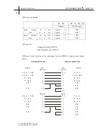
Electric parameters


RC

SD 

RS

CS

DS

ER 


Negative 

Positive logic 

Input        voltage 

level 

+5v      to    +12v 

-5v      to      -12v 

Logical       

0


Logical       

1


ON


OFF


Input        voltage 

level 

+5v      to    +12v 

-5v      to      -12v 

Logical       

0


Logical       

1


ON


OFF


¯


Connector: 

                            Cutting plotter port: DB-25S 

                                    Signal computer port: DB-25P 


¯


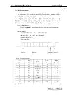
Map  of  serial  interface  cable  connecting  between  IBM-PC  computer  and  cutting 

plotter


Cutting plotter port                                              Signal computer port 


Signal                          pin                                              pin           


Signal 

Chassis GND
Signal  GND

RX Data
TX Data

RTS

DTR

Chassis GND

RX Data
TX Data

GND
RTS

DTR

DB25B

1
7
2
2
4

20

DB25B

1
2
3
7
4

20

DB25P

N/C

7
3
3
5
8
6

20

DB9P

N/C

2
3
5
7
8
4
6

Shield

Signa GND

TX Data
RX Data

CTS
DCD
DSR

Shield

TX Data
RX Dats

GND
RTS
CTS
DTR
DSR


Features of interface                                                                         

PCUT SERIES USER

S    MANUAL


Summary of Contents for CT1080

Page 1: ...Setup 5 3 1 Installation and connection 5 3 2 Install cutting tool 6 4 Features 7 5 USB interface setup 9 6 Operating instructions 14 6 1 Name and functions of parts 14 6 2 Basic operation 16 6 3 Oper...

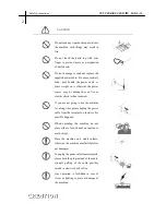
Page 2: ...ircle specifies the acts to be forbidden The symbol in the left tells you no detachment WARNING Do not use the power source not meeting rating voltage otherwise fire or electric shock may be resulted...

Page 3: ...you are not going to use the machine for a long time please unplug the power cable from the receptacle otherwise fire possibly happens When operating the machine do not place either of your hands on c...

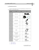
Page 4: ...find anything missing Serial No Item Quantity Icon 1 Power cord 1 2 RS232 USB 1 3 Knife holder 1 4 tungsten knife 3 5 M bracket 1 6 manual 1 7 Wentai software optional 1 8 Cutting plotting master opt...

Page 5: ...nimum width of 1000mm only Take parts of the foot stool out of the pack open the parts bag install the foot stool as the map shows After installation place the host on the support with screw hole targ...

Page 6: ...g when the power is on to avoid damage to the machine Place the machine on a stable surface otherwise the machine may fall therefore get damaged 3 1 1 Place the cutter in a plane and roomy place 3 1 2...

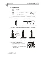
Page 7: ...ing length of the knife top as required for specific cutting media Correct Too long protruding Too short protruding length of knife tip length of knife tip 3 2 3 1 Loosen the screw of tool carrier 2 A...

Page 8: ...hine RS 232 Serial Interface RS 232 Serial Interface meets features of ELA Electric Industries Association General features Standard CCITT V14 EIA RS 232C JIS 5101 Baud rate 300 600 1200 4800 9600baud...

Page 9: ...P Map of serial interface cable connecting between IBM PC computer and cutting plotter Cutting plotter port Signal computer port Signal pin pin Signal Chassis GND Signal GND RX Data TX Data RTS DTR Ch...

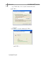
Page 10: ...ace setup 1 Place the include CD ROM in the CD ROM driver connecting USB cable to minicut and pc Window will POP UP hardware wizard screen Log click PCUT SERIES USER S MANUAL USB instructions 9 PC end...

Page 11: ...Log Install form a list or specific location Advanced chick Log locate CD ROM diver click USB instructions PCUT SERIES USER S MANUAL 10...

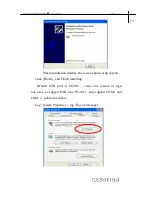
Page 12: ...Click Finish and Finish installing Default USB port is COM 3 some old version of sign soft wave no support USB like WenTai only support COM 1 and COM 2 solution is follow Log system Properties log Dev...

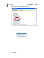
Page 13: ...Select COM 1 or COM 2 click right mouse button Click disable USB instructions PCUT SERIES USER S MANUAL 12...

Page 14: ...Log USB serial port COM3 click right mouse button Log advanced Set com port Number COM 1 or COM 2 _Done_ PCUT SERIES USER S MANUAL USB instructions 13...

Page 15: ...Upper cover 13 Y Transmission Shaft 4 Beam 14 Scale 5 Tooth profile transmission belt 15 Strip cushion 6 LCD Liquid Crystal Display 16 Trimming groove 7 Control keyboard 17 Slider 8 Right cabinet 18 K...

Page 16: ...on 9 Origin setting button 3 Knife raising button 10 Paper feeding button 4 Leftward button 11 Systemic parameter setting button 5 Paper withdrawal button 12 Pause 6 Rightward button 13 Value 7 Online...

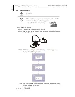
Page 17: ...2 1 2 Plug the cable into the receptacle of the host power source press the power on off on the left ON 6 2 1 3 LCD in the control panel is ON and displays the initializing process of the host and sho...

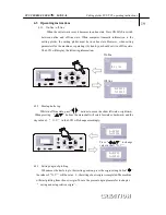
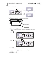
Page 18: ...propriate length from the front of the host Using roll of media Using single sheet of media Pulling it out to required length Cutting required length from paper roll 6 2 2 3 Adjust horizontal position...

Page 19: ...ly cut a small square from the media X 00000 Y 00000 X 00000 Y 00000 6 2 3 3 Take off the square if you fail the square need to be further cut because the press is low or the protruding length of knif...

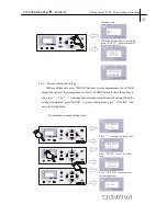
Page 20: ...top While in off line state press buttons to move the slider leftward or rightward When pressing buttons the main shaft will rotate forward or backward and the step value of X Y in the LCD will chang...

Page 21: ...in off line state press DN button the knife will fall then press UP button to raise the knife Press to drop the knife Press to raise the knife 6 3 5 RESET Press RESET button the machine will reinitia...

Page 22: ...ers Press MODE button to show the options in urn press or to change the parameter value of selected option When the setting is completed press PAUSE to escape setting mode press ON LINE and save the s...

Page 23: ...ale 25637 X 00000 Y 00000 In off line state Knife press setting interface Self Test setting interface Setting interface of repeat cutting Speed setting interface X axis setting interface Y axis settin...

Page 24: ...the machine runs if the knife press is found unsuitable press PAUSE button then press or to make press up or down Press 087 Press 110 press or to make press up or down 6 3 7 2 Setting Self Test inter...

Page 25: ...8 Press button to increase cutting copies Press ON LINE to start cutting 6 3 7 4 Cutting speed In speed setting mode press or to adjust cutting speed high speed is suitable for cutting big characters...

Page 26: ...rily in X axis or Y axis state press to increase the value Notes when using this function meticulous adjustment to specific speed and media is desirable 5 3 7 6 Readjustment of initial value When clie...

Page 27: ...length 20000mm 20 Maximum cutting thickness 1mm Knife press 0 800g digital adjustment Mechanism precision 0 1mm Repeatable precision 0 1mm Type of tool Tungsten blade Type of plot pen Atom plot pen a...

Page 28: ...tting speed shall be adjusted according to size of character Generally to cut small glossy characters with high requirement for precision the speed shall not exceed 40 In most cases the speed at the s...

Page 29: ...In case of no display check whether the power work well 2 If black blocks are displayed check whether voltage is at required level If troubles remain after the above operation please contact maintena...

Page 30: ...broken For new ones the nick is thin in the instant glue while for old ones the nick is thick and impressive To resolve it replace it with a new knife 7 16 Question what is attentive when cutting big...

Page 31: ...still fails to be solved after the above operation please contact local agent or maintenance center 7 19 Question Why does the plotter come to halt Answer because it encounters vibrate for a long per...

Reviews: