background image

Phase 12:

27

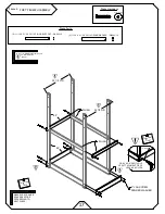
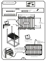
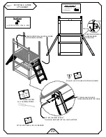
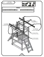
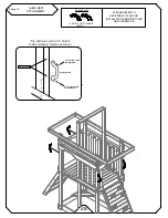
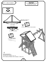
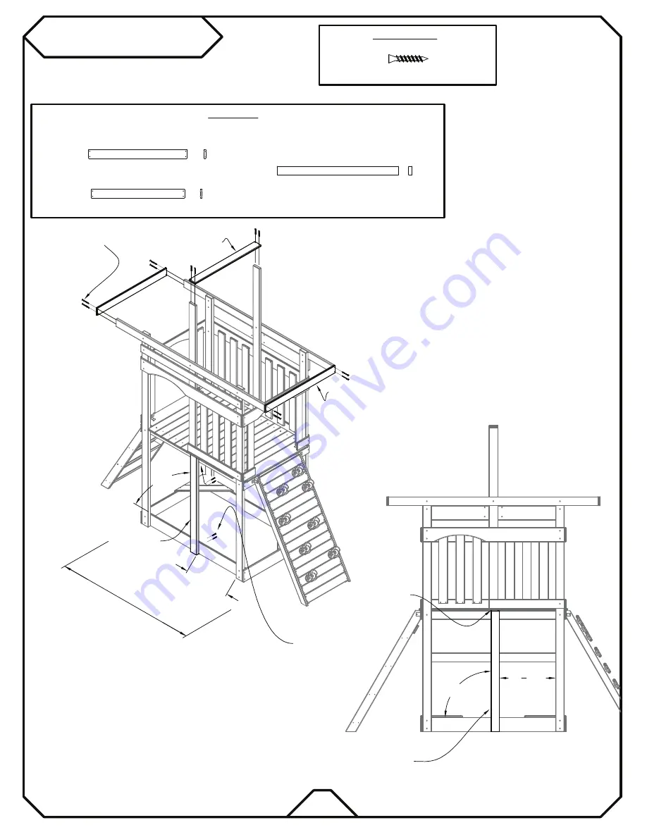
TARP SUPPORTS

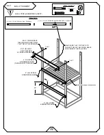
LUNCH TABLE UPRIGHT

Phase Parts

Phase Hardware

WA004-10

WA003-10

WE002-10

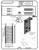
21 1/4" I.D.

ATTACH THROUGH

GROUND BOARD

INTO 'WE002-10'

1 1/2"

T-20 

Deck Screws

(16)

(2) 11/16 X 3 1/2 X 37 1/2 TARP SUPPORT - WA003-10

(1) 11/16 X 3 1/2 X 35 1/2 TARP SUPPORT - WA004-10

(1) 1 3/8 X 3 3/8 X 46 1/4 TABLE UPRIGHT - WE002-10

90°

FIT

UNDER FLOOR

WE002-10

DECK SCREWS

2114 I.D.

90°

SIDE

3

Summary of Contents for Sky View 3101

Page 1: ...SKY VIEW GYM Model 3101...

Page 2: ...8 8 8 8 8 8 Creative Cedar Designs...

Page 3: ...HELP WITH WHAT YOU NEED For more efficient service please log onto our website at www creativecedardesigns com and fill out a request for missing or damaged parts A completed product registration is a...

Page 4: ...rovided to help you in your installation continued satisfaction and safe operation of your Creative Cedar Designs purchase Always keep the safety of your children in mind as your play structure is bei...

Page 5: ...Playcenter in an area that is convenient for adults to watch children at play 6 Create a site free of obstacles that could cause injuries such as low overhanging tree branches overhead wires tree stum...

Page 6: ...p you understand more clearly the installation process and help to eliminate unnecessary mistakes 7 Pay close attention to the diameter and length of each bolt and screw 8 Swing hangers should be buri...

Page 7: ...Standard Specification of Impact Attenuation of Surfacing Materials within the Use Zone of Playground Equipment The following chart explains the fall height in feet from which a life threatening head...

Page 8: ...ren to look before they slide to make sure no one is at the bottom 12 Instruct children to never run up a slide as this increases their chances of falling 13 The parents should have the children dress...

Page 9: ...rts 6 For rusted areas on metallic members such as monkey bars hand supports brackets etc sand and repaint using a non lead based paint meeting the requirements of Title 16 CRF Part 1303 7 Inspect woo...

Page 10: ...ecause children may deliberately jump from a moving swing the shock absorbing material should extend in the front and rear of a swing a minimum distance of 2 times the height of the pivot point measur...

Page 11: ...ildren Do not allow children to play with them and dispose of them immediately when empty CAUTION Unassembled parts may be a choking hazard to children 3 years and younger WARNING CHOKING HAZARD Adult...

Page 12: ...itten steps may include important information not shown in the illustrations 4 Pay close attention to the Items needed and Hardware needed sections of each phase They can be a valuable aid when sortin...

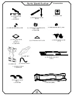
Page 13: ...10 4 11 16 X 3 1 2 X 6 1 2 WALL RAIL WA008 10 13 11 16 X 3 1 2 X 27 WALL SLAT WA009 10 5 11 16 X 3 1 2 X 22 ROCKWALL ROCK BRD WA010 10 3 11 16 X 3 1 2 X 22 ROCKWALL ROCK BRD WA011 10 7 11 16 X 3 1 2...

Page 14: ...1 2 X 20 LADDER STEP WC006 10 2 1 X 3 1 2 X 35 TABLE LEG WC007 10 2 1 X 3 1 2 X 17 TABLE BRACE WC008 10 2 1 X 3 1 2 X 10 TABLE BRACE WC009 10 1 1 X 5 1 2 X 54 SWING BEAM CROSS BRACE WD001 10 4 1 3 8 X...

Page 15: ...D TAG w HDW 2 4 COUNT BAGS CLIMBING ROCKS BP011 GYBR 2 PAIR SAFETY HANDLE BP007 Y 4 SWING HANGER w HDW KC 003 2 STANDARD SWING SEAT BP010 Y 1 GLIDER SEAT 2 GLIDER ARM 1 GLIDER BP 018 GY w HARDWARE 4 C...

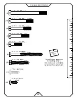
Page 16: ...2 5 16LS31 2 5 16 x 3 1 2 Lag Screws 2 12 5 16 x 2 1 4 Hex Bolts 5 16HB21 4 5 16LS2 5 16 x 2 Lag Screws 37 14TS3 4 3 4 Tapping Sc rews 20 6 5 16 x 2 Hex Bolts 5 16HB2 6 5 16 x 4 Hex Bolts 5 16HB4 1 T...

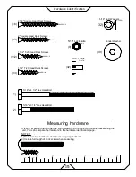
Page 17: ...u get the right hardware in the correct place when assembling the unit You can compare the hardware to the hardware identification page 15 2 5 16 x 3 1 4 Hex Head Bolt 1 5 16 x 4 1 2 Hex Head Bolt 1 1...

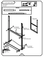
Page 18: ...4 GROUND BOARD WB001 10 2 1 X 3 1 2 X 54 FLOOR BRD WC001 10 4 1 3 8 X 3 3 8 X 89 1 2 FORT UPRIGHT WE001 10 8 5 16 x 2 1 4 Hex Bolts 4 5 16 x 2 1 2 Hex Bolts 2 1 4 HEX BOLT SPLIT WASHER FENDER WASHER B...

Page 19: ...Important MAKE SURE FRAME IS SQUARE BEFORE PROCEEDING TO NEXT PHASE 1 8 Drill Bit Note Important DRILL 1 8 PILOT HOLE USE ATTACHMENT PIECE HOLE AS A GUIDE 2 11 16 X 3 1 2 X 35 1 2 FLOOR SUPPORT WA001...

Page 20: ...LOOR LAYOUT WB005 10 WB005 10 2 3 4 TAPPING SCREW IN EACH BRACKET 1 1 4 DESK SCREWS 2 SCREWS INTO EACH END FLOOR BOARD 1 SCREW INTO ALL OTHER FLOOR BOARDS 1 11 16 X 3 1 2 X 54 FLOOR BRACE WA005 10 2 G...

Page 21: ...OF THE UPRIGHT 2 1 2 HEX BOLT SPLIT WASHER FENDER WASHER 2 LAG SCREW FENDER WASHER THROUGH BOTTOM HOLE 2 5 16 T nuts 8 Fender Washer 2 5 16 Split Washers Phase Hardware 2 5 16 x 2 1 2 Hex Bolts 2 LAG...

Page 22: ...AFETY TABLE SLAT WA014 10 1 1 X 3 1 2 X 54 3 8 LADDER RAIL LEFT WC004 10 1 1 X 3 1 2 X 54 3 8 LADDER RAIL RIGHT WC005 10 4 1 X 3 1 2 X 20 LADDER STEP WC006 10 WC006 10 WC004 10 WC005 10 2 1 2 DECK SCR...

Page 23: ...KWALL RAIL LEFT WSF002 10 ROCK ATTACHMENT 1 4 20 x 1 1 4 Hex Head Bolt 1 4 Split Washer 1 4 20 T Nut 1 4 Washer Climbing Rock 2 4 COUNT BAGS CLIMBING ROCKS BP011 GYBR 23 5 8 O D WA012 10 PUSH ALL BOAR...

Page 24: ...OR FLR SUP 1 TRUSS HEAD SCREW THROUGH BRACKET INTO RAIL 3 4 14 TAPPING SCREW THROUGH BRACKET INTO FLOOR SUPPORT CENTER ROCKWALL DECKLADDER IN THE AREAS SHOWN POSITION ROCKWALL DECKLADDER AS SHOWN DO N...

Page 25: ...WB002 10 WB001 10 ATTACH THIS RAIL FIRST THEN ALIGN THE OTHER RAILS FLUSH WITH IT S TOP EDGE TOP WALL RAILS ARE FLUSH WITH EACH OTHER 1 11 16 X 3 1 2 X 54 WALL RAIL WA006 10 4 5 16 T nuts 4 5 16 Split...

Page 26: ...IT WASHER FENDER WASHER 6 5 16 T nuts 6 Fender Washer 6 5 16 Split Washers Phase Hardware 4 5 16 x 2 1 2 Hex Bolts 2 1 2 HEX BOLT SPLIT WASHER FENDER WASHER 2 5 16 x 2 Hex Bolts 1 1 2 T 20 Deck Screws...

Page 27: ...REST RAIL ON FLOOR AND LAG SCREW INTO CENTER OF UPRIGHT FACE WA007 10 REST RAIL ON FLOOR AND LAG SCREW INTO CENTER OF UPRIGHT FACE OPENING EDGE SHOULD BE FLUSH WITH OPENING EDGE OF TARP UPRIGHT DECK S...

Page 28: ...ET DETAIL L BRACKET 3 4 TAPPING SCREW WALL SLAT FLOOR 3 4 Tapping Screws 10 5 GREEN L BRACKET SMALL M002 2 23 4 3 3 BRACKET SIDES 3 VIEW FROM INSIDE 23 4 3 3 23 4 3 3 SIDES 4 VIEW FROM INSIDE Importan...

Page 29: ...WE002 10 21 1 4 I D ATTACH THROUGH GROUND BOARD INTO WE002 10 1 1 2 T 20 Deck Screws 16 2 11 16 X 3 1 2 X 37 1 2 TARP SUPPORT WA003 10 1 11 16 X 3 1 2 X 35 1 2 TARP SUPPORT WA004 10 1 1 3 8 X 3 3 8 X...

Page 30: ...ETY HANDLE BP007 Y Pre drill holes with a 1 8 drill bit Install all safety handles as shown 1 3 4 Wood Screw Flat Washer Safety Handle 1 8 Pilot Hole 1 3 4 Wood Screw 8 Flat Washer PLEASE REFER TO ACC...

Page 31: ...EFERENCE VIEW SWING BEAM SWING END BEAM 4 HEX BOLT FENDER WASHER FENDER WASHER LOCK NUT 90 5 16 x 3 1 2 Lag Screws 2 9 5 16 Lock Nuts 6 5 16 x 4 Hex Bolts FENDER WASHER LOCK NUT 3 1 2 LAG SCREW 5 16 F...

Page 32: ...ER ATTACHING CHAIN STEP 2 1 PAIR GLIDER BRACKET BP 020 2 STANDARD SWING SEAT BP010 Y 1 GLIDER SEAT 4 CHAIN w EYE BOLT 7 1 2 HEX BOLT 3 4 WASHER 1 2 LOCK NUT 3 4 WASHERS 1 2 LOCK NUT 7 8 WASHERS EYE BO...

Page 33: ...Hex Bolts 4 Fender Washer 4 5 16 Split Washers Phase Hardware 4 5 16 T nuts CreativeCedarDesigns com 2 3 4 Tapping Screw 1 ID Tag 1 1 4 HEX BOLT 5 16 SPLIT WASHER FENDER WASHER Important Note HAND TI...

Page 34: ...Hardware 1 FORT TARP GREEN DO NOT OVER TIGHTEN TAPPING SCREWS Important Note SIDE Important Note HAND TIGHTEN ALL TAPPING SCREWS PLEASE REFER TO THE HARDWARE INCLUDED WITH YOUR TARP 3 4 TAPPING SCREWS...

Page 35: ...ase Parts 2 GREEN L BRACKET SMALL M002 211 4 FLUSH 21 1 4 I D Phase Hardware 1 Truss Head Screw 4 LEGS ARE TO BE LEVEL WITH EACH OTHER AND RESTING ON THE GROUND FLUSH WITH INSIDE OF UPRIGHTS 1 Truss H...

Page 36: ...r 4 5 16 Split Washers Phase Hardware 4 5 16 x 2 Hex Bolts TABLE ASSEMBLY Phase 19 WC008 10 WC009 10 2 Square Head Deck Screws 28 5 11 16 X 3 1 2 X 21 1 4 SAFETY TABLE SLAT WA014 10 MAKE SURE BRACES A...

Page 37: ...Phase 20 SLIDE ATTACHMENT Phase Hardware 8 WAVE SLIDE GREEN Phase Parts 35 3 1 Truss Head Screws 3 1 Truss Head Screws...

Page 38: ...olt screw and nut is tight Make sure every board is secure Make sure the fort is level and enjoy your playset STAKE STAKE STAKE STAKE 36 Phase Hardware Phase Parts 4 1 1 2 LAG BOLT 4 FLAT WASHER 4 ANC...

Page 39: ...en damaged by acts of God negligence misuse or accident or which have been modified or repaired by unauthorized persons b the cost of labor c the cost of shipping the product any part or any replaceme...

Page 40: ...description of the warranty issue 3 Photos of warranted parts and of the entire play system If any of the above steps are not completed there may be delays in the completion of your claim or possibly...

Page 41: ..._______________ City State Zip Code ___________________________________________________ Phone ________________________________________________________________ Date of Purchase ________________________...

Page 42: ...stration Card along with a copy of the receipt and return to Creative Cedar Designs within 30 days of original purchase in order to validate time of purchase for warranty FOLD HERE Place Stamp Here Cr...

Reviews: