background image

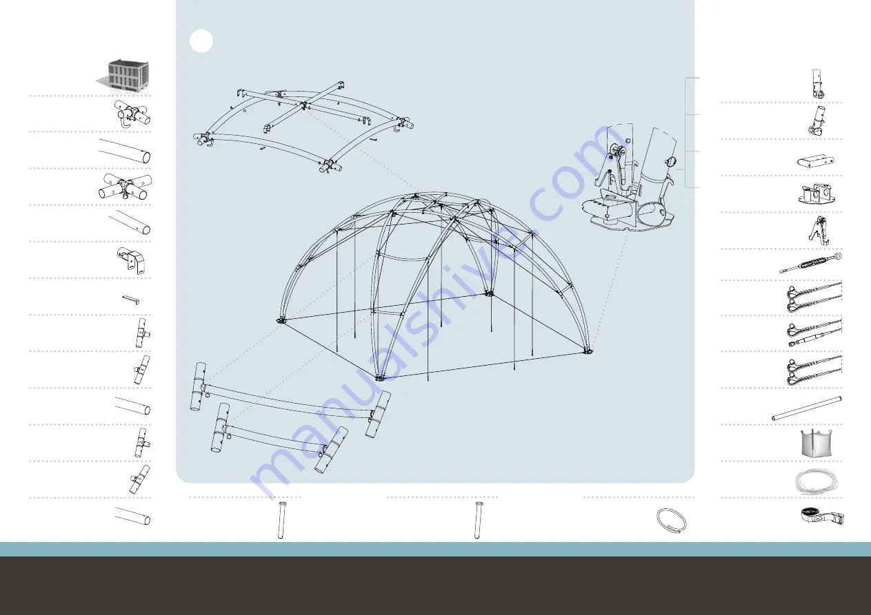
CS-0049 

Main profile 

ø90 mm - 219 cm 

CS-0050 

X-connector

28x

4x

1x

4x

4x

4x

70x

30x

110x

1x

4x

4x

4x

4x

4x

4x

CS-0334 

Sub frame 

center

CS-0335

Sub frame 

beam ø70 mm - 108 cm

CS-0055 

Lower sub profile 

ø70 mm - 101 cm

CS-0054 

Upper sub profile 

ø70 mm - 179 cm

CS-0093 

Locking pin (medium)

ø90 mm profile

CS-0105 

Locking pin (small)

ø70 mm profile

CS-0248 

Securing ring

CS-0336 

Sub frame 

connector

CS-0337 

Locking strip

CS-0052 

T-Connector Lower Left

Marked with “LL”

CS-0051 

T-Connector Upper Left

Marked with “UL”

CS-0057 

T-Connector Lower Right

Marked with “LR”

CS-0056 

T-Connector Upper Right

Marked with “UR”

Crossover L

BOX CONTENTS

CS-0233

Transportbox

CS-0058 

Foot connector Left

4x

4x

4x

4x

1x

1x

4x

8x

8x

4x

16x

CS-0108 

Foot connector Right

CS-0099 

Anchor slide

CS-0148 

Anchor support

CS-0497

Pull bar

CS-9012

Big Bag

CS-9013

Rope 20 m.

CS-0236 

Ratchet plate

CS-9009 

Turn buckle

CS-0234 

Tensioning 

 cable

CS-0235 

Positioning 

cable

CS-0086 

Main 

cable

4x

1x

CS-9037

Strap 4 m.

L

3 | 32

2 | 32

Crossover L

Building instructions 

www.creative-products.nl

Crossover L 

Building instructions 

www.creative-products.nl

Summary of Contents for Crossover L

Page 1: ...CrossoverL Installation Version 3 1 ...

Page 2: ...with LL CS 0051 T Connector Upper Left Marked with UL CS 0057 T Connector Lower Right Marked with LR CS 0056 T Connector Upper Right Marked with UR Crossover L BOX CONTENTS CS 0233 Transportbox CS 0058 Foot connector Left 4x 4x 4x 4x 1x 1x 4x 8x 8x 4x 16x CS 0108 Foot connector Right CS 0099 Anchor slide CS 0148 Anchor support CS 0497 Pull bar CS 9012 Big Bag CS 9013 Rope 20 m CS 0236 Ratchet plat...

Page 3: ... body Secure all parts with locking pins long version and securing rings Main profile CS 0049 X connector CS 0050 X connector CS 0050 Hooks have to point inwards Main profile CS 0049 Main profile CS 0049 STEP 1 Upper main profile CS 0049 X connector CS 0050 X connector CS 0050 Secure all parts with locking pins long version and securing rings ...

Page 4: ...ve products nl Locking strip CS 0337 4x Securing ring CS 0248 4x Mount sub frame at frame body STEP 3 Pre assemble the sub frame Sub frame center CS 0334 Secure all parts with locking pins short version and securing rings Joint has to point downwards Sub frame beam CS 0335 4x Sub frame connector CS 0336 4x STEP 2 ...

Page 5: ...d for two lifting methods 1 Lifting from below for example with a traverse lift by using the subframe Requirements lifting device minimum lifting height 6 meter minimum save working load 300 kg 2 Lifting from above for example with a crane by using lifting slings 2 meter 1000 KG and the hooks of the X connectors LIFTING Note this lifting methode requires more height for building Main cable 4x per ...

Page 6: ...el of main profiles STEP 5 Secure all parts with locking pins long version and securing rings Pre assemble the upper sub profiles 4x STEP 6 Upper long sub profile CS 0054 T Connector Upper Right Marked with UR CS 0056 T Connector Upper Left Marked with UL CS 0051 Curvature has to point downwards backwards Locking pin Short version CS 0105 2x Securing ring CS 0248 2x UL UR ...

Page 7: ...l Crossover L Building instructions www creative products nl Mount the upper sub profiles 4x Mount the second end of the 8 inner main cables STEP 7 STEP 8 Secure all parts with locking pins long version and securing rings Curvature sub profiles has to point inwards UL UR ...

Page 8: ...ossover L Building instructions www creative products nl Mount the first end of the tensioning cables STEP 9 Secure all parts with locking pins long version and securing rings Mount the second level of main profiles STEP 10 Main profile CS 0049 8x Tensioning cable CS 0234 8x ...

Page 9: ...ts with locking pins long version and securing rings Pre assemble the lower sub profiles 4x STEP 11 Curvature sub profiles has to point inwards Curvature sub profiles has to point inwards LL LR Locking pin Short version CS 0105 2x Securing ring CS 0248 2x Lower short sub profile CS 0055 T Connector Lower Right Marked with LR CS 0057 T Connector Lower Left Marked with LL CS 0052 LL LR ...

Page 10: ...ducts nl Crossover L Building instructions www creative products nl Mount the second end of the 8 remaining main cables STEP 13 Mount the last level of main profiles STEP 14 Secure all parts with locking pins long version and securing rings Main profile CS 0049 8x ...

Page 11: ...ter mounting the positioning cables the structure can be placed on its feet Pull the legs of the structure outwards to put the positioning cables under tension Mount the positioning cables STEP 16 Foot connector Left CS 0058 Foot connector Right CS 0108 Anchor slide CS 0099 Anchor support CS 0148 Mount the feet 4x STEP 15 Secure all parts with locking pins long version and securing rings Hooks hav...

Page 12: ...ension the 8 tension cables By tensioning the tension cables all the cables in the structure get tensioned and the structure gets its rigidity STEP 18 Anchor the structure STEP 17 For the different anchoring options and instructions see the anchoring guide After anchoring the positioning cables can be removed Use the inner hooks of the feet ...

Page 13: ...nl Guide the cover on both sides Place the cover over the structure The included rope can be used to pull the cover over the structure Tie the rope to the lifting eye Place the pull bars in the loops of the cover corners STEP 19 STEP 20 Do not place the cover in windy conditions or take decent security measures Pull bar CS 0489 ...

Page 14: ...ng instructions www creative products nl Turn buckle CS 9009 8x Use the outer hooks of the feet Tension the contours of the cover with the turn buckles STEP 22 Ratchet plate CS 0236 Tension the cover at the corners Use the the seams of the cover to align the cover with the structure STEP 21 ...

Page 15: ...f the structure The 5 hooks now can be demounted 3 Tension the side panel with the lashings at the bottom Tension the outer lashings to the structure feet and the inner lashings to the ground Side panel CS 0402 Inside Connection gutter CS 0270 For the different anchoring options and instructions see the anchoring guide Mount the side panels if desired Mount the connection gutter if desired Close t...

Page 16: ...31 32 30 32 Crossover L Building instructions www creative products nl Crossover L Building instructions www creative products nl ...

Page 17: ...Gewenten 43a 4704 RE Roosendaal The Netherlands T 31 0 165 51 07 77 CS BI COL V3 1 info creative products nl www creative products nl Installation movie Crossover L ...

Reviews: