background image


Guangzhou Creator electronics Ltd. Co


2012-01


WWW.CREATOR1997.COM


User’s Manual of WiFi Conference System 


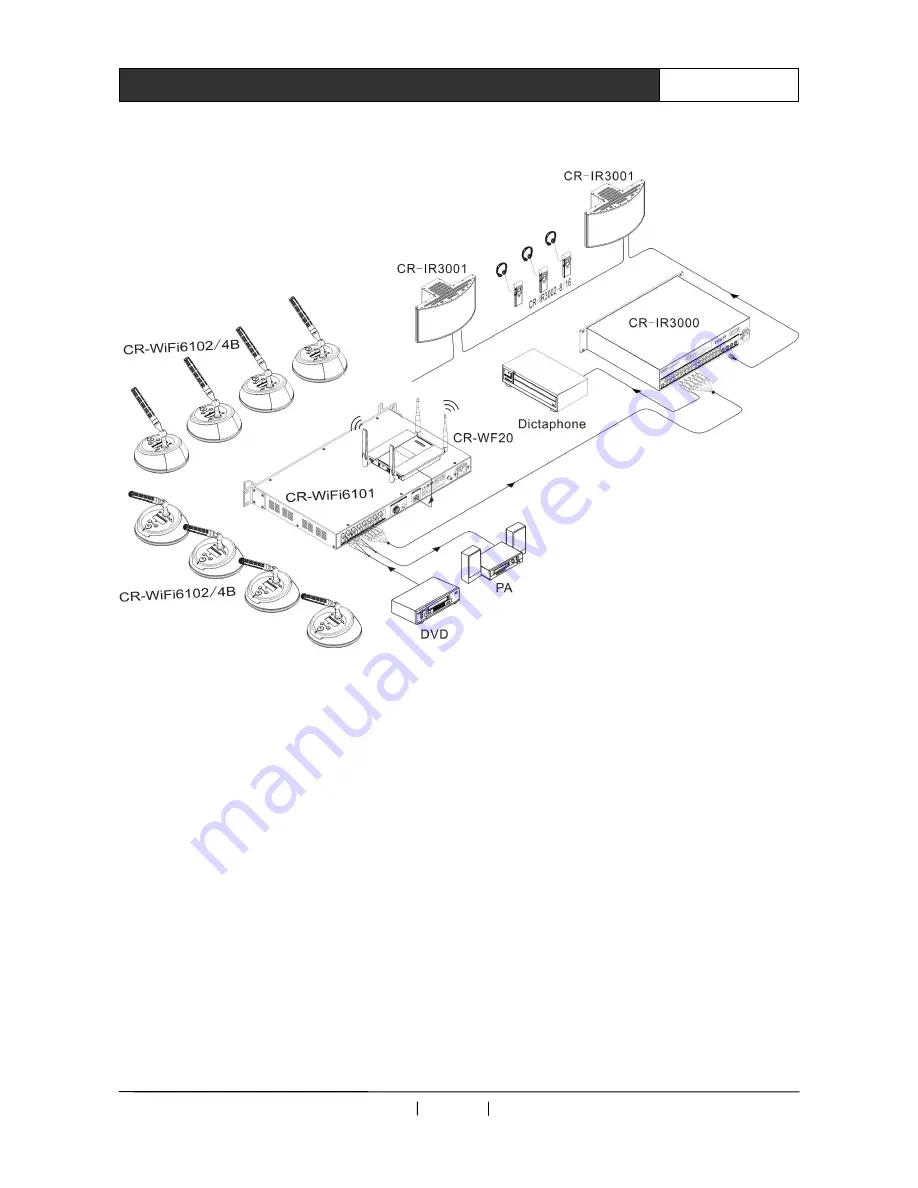
2.9    System Connection Diagram 


Summary of Contents for CR-WiFi6101

Page 1: ...U Us se er r s s M Ma an nu ua al l o of f W Wi iF Fi i C Co on nf fe er re en nc ce e S Sy ys st te em m V1 1 CREATOR CHINA ...

Page 2: ...o remind the user that the risky uninsulated voltage in the device could caused electric shock to human CE authentication indicates the product is in line with the EU safety regulation and for assurance of safety use SGS Authentication indicates the product has reached the QC standard of the global biggest Swiss universe surveyor This product has acquired the ISO9001 International Quality Authenti...

Page 3: ...ns with strong interference shielded cable should be used for the input and output of HF signal to improve the anti interference performance of the system Note in Wiring Installation and wiring shouldn t be conducted until external electric power is cut off otherwise electric shock or device damage could happen The product is grounded by the earth lead of the power cable To avoid electric shock th...

Page 4: ...gloves Note for declaration of worthless Explosion of electrolytic capacitor on the circuit board could happen when burning it Please classify and dispose it Don t dispose it into household garbage Please deal it as industrial waste or in accordance with local environmental protection regulation ...

Page 5: ...ce the date of release any function or relevant parameter alteration will be in supplement instruction Please refer to the manufacturer or dealers for inquiry CREATOR Electronics own the copyright of the Manual Without permission any unit or person shall not take part or total of the Manual for business purpose The copyright of the Manual is protected by Copyright Law of People s Republic of China...

Page 6: ...tion System 6 2 7 Host Installation of CR WiFi6101 7 2 8 CR WiFi6101 Technical Parameters 7 2 9 System Connection Diagram 8 Chapter 3 WiFi Conference Unit 9 3 1 Overview 9 3 2 CR WiFi6102 4B Panel Instruction 9 3 3 CR WiFi6102 4B Functions and Features 10 3 4 CR WiFi6102 4B Operation Instruction 10 3 4 1 CR WiFi6102 4B Setup 10 3 5 CR WiFi6102 4B Technical Parameters 11 Chapter 4 Accessories 12 4 ...

Page 7: ...ashionable and decent design Not limited by space with quick installation without influencing the site WiFi conference system is for use right after installation only needing for placing on the conference table whatever at which sites After use it can be packed and moved No shield No interference Standard 802 11n WiFi technology with strong penetration not influenced by the move of staff Complete ...

Page 8: ...Guangzhou Creator electronics Ltd Co 2012 01 WWW CREATOR1997 COM 2 User s Manual of WiFi Conference System 1 4 System Diagram ...

Page 9: ...controlled With multiple conference modes selection optional speaker number and speech modes super powerful expanding function DSP audio process adopting equalizer module environmental noise suppression technology compatible with CREATOR simultaneous interpretation system realizing modern high tech conference 2 2 CR WiFi6101 Panel Instruction Front Panel Rear Panel 1 Power Switch 2 POWER Power ind...

Page 10: ... setup the value needed 14 ENTER Enter execution key for confirmation of all operations 15 IN Audio input port connecting to external audio devices like those providing background music or remote teleconference terminal output 16 OUT Audio output port is for connecting to amplifier to increasing the voice of speakers or connecting to device for recording 17 OUTPUTS Audio output port with 0 12 chan...

Page 11: ...g system will auto exit if without any operation for about 10 seconds LCD screen instruction LCD monitor will be kept on for long time before turning on the host and display current system status and operation information with white fonts and blue background Key indicator instruction When key indicator is in red or flashing red indicator flashes for once indicates successful selection of key funct...

Page 12: ...opts CAT 5 category 5 cabling as wiring connecting the network devices via RJ 45 connectors on both ends of CAT 5 The standard connection of UTP is not stipulated freely as symmetric layout of cable connectors has to be ensured In this way the internal interference arising within cables can be offset Generally HSYV has 4 pairs of twisted thin lines inside marked in different colors Two connections...

Page 13: ...upports See the following diagram for installation 2 8 CR WiFi6101 Technical Parameters External control port RJ45 port Display 1602LCD monitor Translation unit port 8Pin avionics port S N 80dB Harmonic distortion 0 5 Over carrier distortion 1 Cross talk attenuation 1KHz 50dB Static power consumption 3W Max power consumption 70W Max power output at 8Pin avionics port 60W Dynamic range 80dB Frequen...

Page 14: ...Guangzhou Creator electronics Ltd Co 2012 01 WWW CREATOR1997 COM 8 User s Manual of WiFi Conference System 2 9 System Connection Diagram ...

Page 15: ...red not to be captured by unauthorized parties 3 2 CR WiFi6102 4B Panel Instruction Top view Bottom view 1 Headset jack insert the phone plug to hear the speech 2 MIC power indicator will be on when MIC switch is on 3 Plugging MIC stand base MIC socket adopting 5 core high density avionics interface with screw turning connector making it stable in connection 4 Unit power switching key press it to ...

Page 16: ...i6102 4B Setup Wireless conference unit comprises ROUTER and IP setup And the Router includes two components of SSID and PASSWORD The following is the instruction in details 3 4 1 1 ROUTER Setup SSID setup Step 1 Access to interface After correctly connecting the device press the ON OFF key on panel LCD monitor will display Startup press and hold MIC key to access to Unit Set Menu screen ROUTER is...

Page 17: ...Setup In Router Set Menu screen press MIC key to exit and access to Unit Set Menu screen press key to access to IP setup screen The operation is the same as that for setup SSID the function of pressing key to delete 0 and the value after it doesn t exist And value changing order is 0 to 9 Factory default IP is 192 168 2 110 IP address ranges between 192 168 2 31 and 192 168 2 254 Host IP address 1...

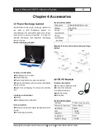
Page 18: ...ress recharging with maximum recharging time of 3 hours Apart from recharging the case can hold the unit Controller and indicator On Off Recharging status indication Inter connection Series port for power supply Europe type male socket 24 recharging contacts Technical Parameters Dimension 497LX397WX120H mm Weight About 5kg Power consumption 100W Power consumption stand by 3W Diagram of series conn...

Page 19: ...d Optional Function description Heart shaped directional Condenser MIC High density 5 core Avionics interface Normal speech indicator Speech application indicator 4 5 Power Recharger of CR DOCK10B Wireless Conference Unit Optional Function Description Power recharge for the speech unit in wireless conference With 4 anti skidding food pads for fastening on the table while recharging in work Power r...

Page 20: ...CREATOR CORPORATION CHINA Copyright by CREATOR Last Revision 01 2012 ...

Reviews: